TOP Contributors

  1. MIKROE (2653 codes)
  2. Alcides Ramos (351 codes)
  3. Shawon Shahryiar (307 codes)
  4. jm_palomino (112 codes)
  5. Chisanga Mumba (90 codes)
  6. S P (73 codes)
  7. dany (71 codes)
  8. MikroBUS.NET Team (35 codes)
  9. NART SCHINACKOW (34 codes)
  10. Armstrong Subero (27 codes)

Most Downloaded

  1. Timer Calculator (136646 times)
  2. FAT32 Library (69857 times)
  3. Network Ethernet Library (55899 times)
  4. USB Device Library (46236 times)
  5. Network WiFi Library (41869 times)
  6. FT800 Library (41099 times)
  7. GSM click (28953 times)
  8. PID Library (26403 times)
  9. mikroSDK (26321 times)
  10. microSD click (25334 times)
Libstock prefers package manager

Package Manager

We strongly encourage users to use Package manager for sharing their code on Libstock website, because it boosts your efficiency and leaves the end user with no room for error. [more info]

< Back
mikroSDK Library

DC Motor click

Rating:

5

Author: MIKROE

Last Updated: 2019-01-28

Package Version: 1.0.0.1

mikroSDK Library: 1.0.0.0

Category: Brushed

Downloaded: 6986 times

Followed by: 3 users

License: MIT license  

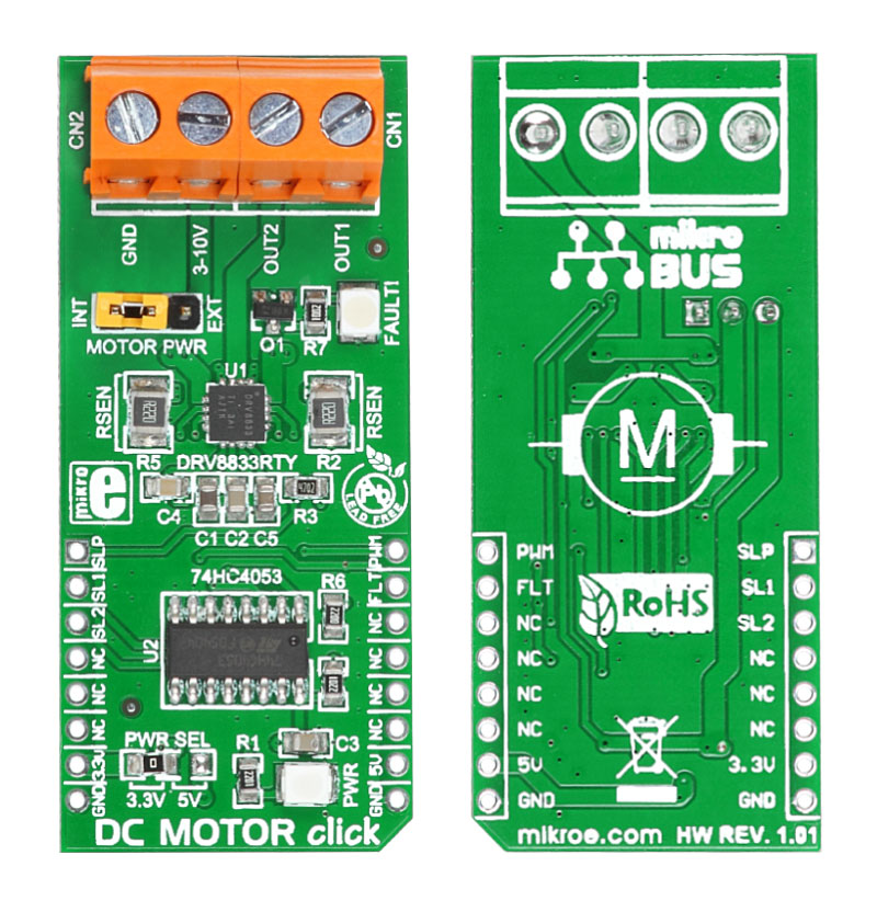
This is a simple demonstration of using the DRV8833 dual bridge motor driver (http://www.ti.com/product/drv8833), which is being used for controlling DC brush motors, a bipolar stepper motor, solenoids, or other inductive loads.

No Abuse Reported

Do you want to subscribe in order to receive notifications regarding "DC Motor click" changes.

Do you want to unsubscribe in order to stop receiving notifications regarding "DC Motor click" changes.

Do you want to report abuse regarding "DC Motor click".

  • mikroSDK Library 2.0.0.0
  • Comments (0)
DOWNLOAD LINK RELATED COMPILER CONTAINS
mikroBasic PRO for ARM
  • lib
  • src
  • exa
  • hlp
  • hex
  • sch
  • pcb
  • doc
mikroBasic PRO for AVR
  • lib
  • src
  • exa
  • hlp
  • hex
  • sch
  • pcb
  • doc
mikroBasic PRO for dsPIC30/33 & PIC24
  • lib
  • src
  • exa
  • hlp
  • hex
  • sch
  • pcb
  • doc
mikroBasic PRO for FT90x
  • lib
  • src
  • exa
  • hlp
  • hex
  • sch
  • pcb
  • doc
mikroBasic PRO for PIC
  • lib
  • src
  • exa
  • hlp
  • hex
  • sch
  • pcb
  • doc
mikroBasic PRO for PIC32
  • lib
  • src
  • exa
  • hlp
  • hex
  • sch
  • pcb
  • doc
mikroC PRO for ARM
  • lib
  • src
  • exa
  • hlp
  • hex
  • sch
  • pcb
  • doc
mikroC PRO for AVR
  • lib
  • src
  • exa
  • hlp
  • hex
  • sch
  • pcb
  • doc
mikroC PRO for dsPIC30/33 & PIC24
  • lib
  • src
  • exa
  • hlp
  • hex
  • sch
  • pcb
  • doc
mikroC PRO for FT90x
  • lib
  • src
  • exa
  • hlp
  • hex
  • sch
  • pcb
  • doc
mikroC PRO for PIC
  • lib
  • src
  • exa
  • hlp
  • hex
  • sch
  • pcb
  • doc
mikroC PRO for PIC32
  • lib
  • src
  • exa
  • hlp
  • hex
  • sch
  • pcb
  • doc
mikroPascal PRO for ARM
  • lib
  • src
  • exa
  • hlp
  • hex
  • sch
  • pcb
  • doc
mikroPascal PRO for AVR
  • lib
  • src
  • exa
  • hlp
  • hex
  • sch
  • pcb
  • doc
mikroPascal PRO for dsPIC30/33 & PIC24
  • lib
  • src
  • exa
  • hlp
  • hex
  • sch
  • pcb
  • doc
mikroPascal PRO for FT90x
  • lib
  • src
  • exa
  • hlp
  • hex
  • sch
  • pcb
  • doc
mikroPascal PRO for PIC
  • lib
  • src
  • exa
  • hlp
  • hex
  • sch
  • pcb
  • doc
mikroPascal PRO for PIC32
  • lib
  • src
  • exa
  • hlp
  • hex
  • sch
  • pcb
  • doc

mikroSDK Library Blog

DC Motor Click Board

DC Motor Click Board

Front and back side appearance of the DC Motor Click Board.

View full image

Library Description

The library covers all the necessary functions to control DC Motor Click board.
DC Motor Click communicates with the target board via PWM module.
This library contains drivers for moving in the left or right direction 
and from slow to the fast speed of rotation, enable the motor and set sleep mode function, 
for diagnostics and PWM function: initialization, for sets duty ratio, starts and stops PWM module.

Key functions:

  • void dcmotor_enable() - Enable the motor function.
  • void dcmotor_leftDirectionFast() - Select left direction, fast decay function.
  • void dcmotor_rightDirectionSlow() - Select right direction, slow decay function.

Examples description

The application is composed of the three sections :

  • System Initialization - Initializes GPIO and LOG structures, sets AN, RST, CS, PWM pins as output
    and INT pin as input.
  • Application Initialization - Initialization driver enable's - GPIO, PWM initialization, set PWM duty cycle and PWM frequency, enable the motor, start PWM and start write log.
  • Application Task - (code snippet) This is a example which demonstrates the use of DC Motor Click board. DC Motor Click communicates with register via PWM interface. It shows moving in the left direction from slow to fast speed and moving in the right direction from fast to slow speed.
    Results are being sent to the Usart Terminal where you can track their changes.
void applicationTask()
{      
    mikrobus_logWrite( " Left Direction ", _LOG_LINE );
    dcmotor_leftDirectionSlow();
    dcmotor_enable();
    Delay_1sec();

    for ( dutyCycle = 500; dutyCycle < 3000; dutyCycle += 250 )
    {
        dcmotor_pwmSetDuty( dutyCycle );
        mikrobus_logWrite( " <", _LOG_TEXT );
        Delay_1sec();
    }

    dcmotor_sleepMode();
    mikrobus_logWrite( "", _LOG_LINE );
    Delay_1sec();
    
    mikrobus_logWrite( "---------------------", _LOG_LINE );
    mikrobus_logWrite( " Right Direction ", _LOG_LINE );
    dcmotor_rightDirectionFast();
    dcmotor_enable();
    Delay_1sec();

    for ( dutyCycle = 500; dutyCycle < 3000; dutyCycle += 250 )
    {
        dcmotor_pwmSetDuty( dutyCycle );
        mikrobus_logWrite( " >", _LOG_TEXT );
        Delay_1sec();
    }

    mikrobus_logWrite( "", _LOG_LINE );
    mikrobus_logWrite( "---------------------", _LOG_LINE );
    dcmotor_sleepMode();
    Delay_1sec();
}


Additional Functions :

  • uint32_t dcmotor_pwmInit(uint16_t freq)- Initializes the Timer module in PWM mode.
  • void dcmotor_pwmSetDuty(uint16_t duty)- The function changes PWM duty ratio.
  • void dcmotor_pwmStart()- Starts appropriate PWM module.
  • void dcmotor_pwmStop()- Stops appropriate PWM module.
     

Other mikroE Libraries used in the example:

  • PWM
  • UART

Additional notes and information

Depending on the development board you are using, you may need USB UART clickUSB UART 2 click or RS232 click to connect to your PC, for development systems with no UART to USB interface available on the board. The terminal available in all MikroElektronika compilers, or any other terminal application of your choice, can be used to read the message.

ALSO FROM THIS AUTHOR

H-Bridge 11 click

0

H-Bridge 11 Click is a compact add-on board that allows a voltage to be applied across a load in either direction. This board features the MAX22200, an octal serial-controlled solenoid and motor driver from Analog Devices. The MAX22200 is SPI-configurable and rated for an operating voltage range from 4.5V to 36V. Each channel features a low impedance push-pull output stage with sink-and-source driving capability up to 1A RMS driving current. Its internal half-bridges can be configured as low-side or high-side drivers, supports two control methods (voltage and current drive regulation), and features a full set of protections and diagnostic functions.

[Learn More]

SHT1x click

0

This code demonstrates how to use SHT1x click board in mikroBUS form factor. SHT11 sensor uses I2C communication and measures temperature and relative humidity.

[Learn More]

Multi Stepper TB62269 click

0

Multi Stepper Click is a compact add-on board that contains a bipolar stepper motor driver. This board features the TB62269FTG, PWM method CLOCK-in controlled bipolar stepping motor driver from Toshiba Semiconductor. It supports a PWM constant-current control drive and allows from full-step up to 1/32 steps resolution for less motor noise and smoother control. It has a wide operating voltage range of 10V to 38V with an output current capacity of 1.2A in addition to several built-in error detection circuits.

[Learn More]