We strongly encourage users to use Package manager for sharing their code on Libstock website, because it boosts your efficiency and leaves the end user with no room for error. [more info]

Rating:
Author: Val Gretchev
Last Updated: 2014-06-26
Package Version: 1.0.0.1
Category: Other Codes
Downloaded: 1183 times
Followed by: 1 user
License: MIT license
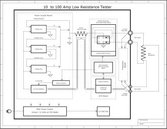
Electrical power generation and distribution companies require an instrument for testing power transformer windings and circuit breaker contact resistance during maintenance. This is a design for such an instrument. The mikromedia 5 for Tiva board is the perfect candidate as the Microcontroller with Touchscreen in the block diagram.
Do you want to subscribe in order to receive notifications regarding "Ultra-Low Resistance Tester (micro Ohm Meter)" changes.
Do you want to unsubscribe in order to stop receiving notifications regarding "Ultra-Low Resistance Tester (micro Ohm Meter)" changes.
Do you want to report abuse regarding "Ultra-Low Resistance Tester (micro Ohm Meter)".
| DOWNLOAD LINK | RELATED COMPILER | CONTAINS |
|---|---|---|
| 1403796159_ultra_low_resist_other_other.zip [1.13MB] | Other Compiler |
|
| 1403800310_ultra_low_resist_other_arm.zip [2.54MB] | Other ARM Compilers |
|
In the electrical power generation and distribution field, maintenance of large transformers and circuit breakers is required on a regular schedule. These essential devices cost a huge amount of money and their health is very carefully monitored. Furthermore, when these devices do not operate at peak efficiency, the power wasted in heat could be substantial.
One instrument used in testing transformer windings and circuit breaker contacts is a micro Ohm meter. The windings and contacts may increase in resistance over time and start dissipating power. This added expense for the company in power lost and the possibility of catastrophic failure of the device make it worthwhile to repair a device before huge expenses are incurred. A history for each device is meticulously kept so that any deviation from the original reading can be dealt with in a timely manner.
As you may expect, the windings and contacts present a very low resistance (40 to 500 micro Ohms) and precise measurement is important. These devices are usually 3-phase, but measurements are made on one phase at a time and the leads are moved from phase to phase until all readings have been performed. The readings are made using a 4-terminal measurement (true 4-terminal Kelvin measurement method) by passing a DC current through the unknown resistance and measuring the voltage drop across it. The resistance is then calculated using Ohm’s Law.

Interconnection between various circuit boards packaged in a Pelican case for strength and durability.
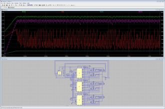
View full imageI ran the Linear Technology simulator on the Low Voltage Power Supply circuit. All the files for simulation are included in the zip file. You can download LTspice at:
http://www.linear.com/designtools/software/
Obviously, the design of the power supply requires some re-thinking. The current control doesn’t work as expected. Some other method for current control will be required.
