TOP Contributors

  1. MIKROE (2653 codes)
  2. Alcides Ramos (351 codes)
  3. Shawon Shahryiar (307 codes)
  4. jm_palomino (112 codes)
  5. Chisanga Mumba (90 codes)
  6. S P (73 codes)
  7. dany (71 codes)
  8. MikroBUS.NET Team (35 codes)
  9. NART SCHINACKOW (34 codes)
  10. Armstrong Subero (27 codes)

Most Downloaded

  1. Timer Calculator (136660 times)
  2. FAT32 Library (69898 times)
  3. Network Ethernet Library (55916 times)
  4. USB Device Library (46248 times)
  5. Network WiFi Library (41881 times)
  6. FT800 Library (41126 times)
  7. GSM click (28970 times)
  8. PID Library (26406 times)
  9. mikroSDK (26343 times)
  10. microSD click (25350 times)
Libstock prefers package manager

Package Manager

We strongly encourage users to use Package manager for sharing their code on Libstock website, because it boosts your efficiency and leaves the end user with no room for error. [more info]

< Back
mikroSDK Library

Button G click

Rating:

1

Author: MIKROE

Last Updated: 2018-11-07

Package Version: 1.0.0.1

mikroSDK Library: 1.0.0.0

Category: Pushbutton/Switches

Downloaded: 3807 times

Followed by: 8 users

License: MIT license  

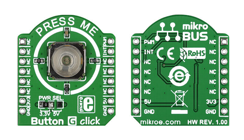
Button G click is the simplest solution for adding a single pushbutton to your design. The button itself is transparent, 6.8mm in diameter and has a green LED backlight. When pressed, it sends an interrupt signal to the target board microcontroller. The backlight LED is controlled separately through the mikroBUSâ„¢ PWM pin.

No Abuse Reported

Do you want to subscribe in order to receive notifications regarding "Button G click" changes.

Do you want to unsubscribe in order to stop receiving notifications regarding "Button G click" changes.

Do you want to report abuse regarding "Button G click".

  • mikroSDK Library 2.0.0.0
  • Comments (1)
DOWNLOAD LINK RELATED COMPILER CONTAINS
mikroBasic PRO for ARM
  • lib
  • src
  • exa
  • hlp
  • hex
  • sch
  • pcb
  • doc
mikroBasic PRO for AVR
  • lib
  • src
  • exa
  • hlp
  • hex
  • sch
  • pcb
  • doc
mikroBasic PRO for dsPIC30/33 & PIC24
  • lib
  • src
  • exa
  • hlp
  • hex
  • sch
  • pcb
  • doc
mikroBasic PRO for FT90x
  • lib
  • src
  • exa
  • hlp
  • hex
  • sch
  • pcb
  • doc
mikroBasic PRO for PIC
  • lib
  • src
  • exa
  • hlp
  • hex
  • sch
  • pcb
  • doc
mikroBasic PRO for PIC32
  • lib
  • src
  • exa
  • hlp
  • hex
  • sch
  • pcb
  • doc
mikroC PRO for ARM
  • lib
  • src
  • exa
  • hlp
  • hex
  • sch
  • pcb
  • doc
mikroC PRO for AVR
  • lib
  • src
  • exa
  • hlp
  • hex
  • sch
  • pcb
  • doc
mikroC PRO for dsPIC30/33 & PIC24
  • lib
  • src
  • exa
  • hlp
  • hex
  • sch
  • pcb
  • doc
mikroC PRO for FT90x
  • lib
  • src
  • exa
  • hlp
  • hex
  • sch
  • pcb
  • doc
mikroC PRO for PIC
  • lib
  • src
  • exa
  • hlp
  • hex
  • sch
  • pcb
  • doc
mikroC PRO for PIC32
  • lib
  • src
  • exa
  • hlp
  • hex
  • sch
  • pcb
  • doc
mikroPascal PRO for ARM
  • lib
  • src
  • exa
  • hlp
  • hex
  • sch
  • pcb
  • doc
mikroPascal PRO for AVR
  • lib
  • src
  • exa
  • hlp
  • hex
  • sch
  • pcb
  • doc
mikroPascal PRO for dsPIC30/33 & PIC24
  • lib
  • src
  • exa
  • hlp
  • hex
  • sch
  • pcb
  • doc
mikroPascal PRO for FT90x
  • lib
  • src
  • exa
  • hlp
  • hex
  • sch
  • pcb
  • doc
mikroPascal PRO for PIC
  • lib
  • src
  • exa
  • hlp
  • hex
  • sch
  • pcb
  • doc
mikroPascal PRO for PIC32
  • lib
  • src
  • exa
  • hlp
  • hex
  • sch
  • pcb
  • doc

mikroSDK Library Blog

Button G click Board

Button G click Board

Front and back view of Button G Click Board.

View full image

ALSO FROM THIS AUTHOR

V to Hz Click

5

V to HZ click is a device that turns analog voltage into a pulse wave signal of a certain frequency.

[Learn More]

GSR click

0

GSR click can be used to measure the electrodermal activity (EDA) of the human body, also known as the galvanic skin response (GSR).

[Learn More]

R Meter click

1

R Meter click is a mikroBUS add-on board with circuitry for measuring the value of resistors. The board can be used to measure a wide range of resistors (from 0 to 1 Mega Ohm) The design is based on a non-inverting amplifier circuit, with the measured resistor placed in a feedback loop that influences the gain of the amplifier.

[Learn More]