TOP Contributors

  1. MIKROE (2650 codes)
  2. Alcides Ramos (350 codes)
  3. Shawon Shahryiar (307 codes)
  4. jm_palomino (112 codes)
  5. Chisanga Mumba (90 codes)
  6. S P (73 codes)
  7. dany (71 codes)
  8. MikroBUS.NET Team (35 codes)
  9. NART SCHINACKOW (34 codes)
  10. Armstrong Subero (27 codes)

Most Downloaded

  1. Timer Calculator (136557 times)
  2. FAT32 Library (69760 times)
  3. Network Ethernet Library (55856 times)
  4. USB Device Library (46198 times)
  5. Network WiFi Library (41818 times)
  6. FT800 Library (41023 times)
  7. GSM click (28934 times)
  8. PID Library (26386 times)
  9. mikroSDK (26297 times)
  10. microSD click (25307 times)
Libstock prefers package manager

Package Manager

We strongly encourage users to use Package manager for sharing their code on Libstock website, because it boosts your efficiency and leaves the end user with no room for error. [more info]

< Back
mikroSDK Library

StereoAmp click

Rating:

0

Author: MIKROE

Last Updated: 2019-04-02

Package Version: 1.0.0.1

mikroSDK Library: 1.0.0.0

Category: Amplifier

Downloaded: 3456 times

Not followed.

License: MIT license  

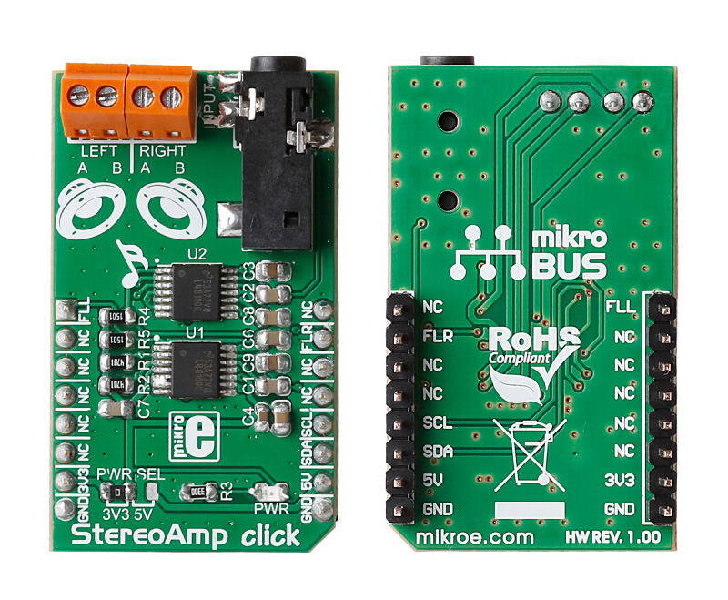
StereoAmp click functions as a stereo amplifier and is ideal for battery powered devices. It features two LM48100Q-Q1 Boomer ICs by Texas Instruments.

No Abuse Reported

Do you want to subscribe in order to receive notifications regarding "StereoAmp click" changes.

Do you want to unsubscribe in order to stop receiving notifications regarding "StereoAmp click" changes.

Do you want to report abuse regarding "StereoAmp click".

  • mikroSDK Library 2.0.0.0
  • Comments (0)
DOWNLOAD LINK RELATED COMPILER CONTAINS
mikroBasic PRO for ARM
  • lib
  • src
  • exa
  • hlp
  • hex
  • sch
  • pcb
  • doc
mikroBasic PRO for AVR
  • lib
  • src
  • exa
  • hlp
  • hex
  • sch
  • pcb
  • doc
mikroBasic PRO for dsPIC30/33 & PIC24
  • lib
  • src
  • exa
  • hlp
  • hex
  • sch
  • pcb
  • doc
mikroBasic PRO for FT90x
  • lib
  • src
  • exa
  • hlp
  • hex
  • sch
  • pcb
  • doc
mikroBasic PRO for PIC
  • lib
  • src
  • exa
  • hlp
  • hex
  • sch
  • pcb
  • doc
mikroBasic PRO for PIC32
  • lib
  • src
  • exa
  • hlp
  • hex
  • sch
  • pcb
  • doc
mikroC PRO for ARM
  • lib
  • src
  • exa
  • hlp
  • hex
  • sch
  • pcb
  • doc
mikroC PRO for AVR
  • lib
  • src
  • exa
  • hlp
  • hex
  • sch
  • pcb
  • doc
mikroC PRO for dsPIC30/33 & PIC24
  • lib
  • src
  • exa
  • hlp
  • hex
  • sch
  • pcb
  • doc
mikroC PRO for FT90x
  • lib
  • src
  • exa
  • hlp
  • hex
  • sch
  • pcb
  • doc
mikroC PRO for PIC
  • lib
  • src
  • exa
  • hlp
  • hex
  • sch
  • pcb
  • doc
mikroC PRO for PIC32
  • lib
  • src
  • exa
  • hlp
  • hex
  • sch
  • pcb
  • doc
mikroPascal PRO for ARM
  • lib
  • src
  • exa
  • hlp
  • hex
  • sch
  • pcb
  • doc
mikroPascal PRO for AVR
  • lib
  • src
  • exa
  • hlp
  • hex
  • sch
  • pcb
  • doc
mikroPascal PRO for dsPIC30/33 & PIC24
  • lib
  • src
  • exa
  • hlp
  • hex
  • sch
  • pcb
  • doc
mikroPascal PRO for FT90x
  • lib
  • src
  • exa
  • hlp
  • hex
  • sch
  • pcb
  • doc
mikroPascal PRO for PIC
  • lib
  • src
  • exa
  • hlp
  • hex
  • sch
  • pcb
  • doc
mikroPascal PRO for PIC32
  • lib
  • src
  • exa
  • hlp
  • hex
  • sch
  • pcb
  • doc

mikroSDK Library Blog

StereoAmp click

StereoAmp click

Front and back view of the StereoAmp click board.

View full image

Library Description

The library covers all the necessary functions to control StereoAmp Click board. A library has drivers for set volume, enable and disable amplifier function, set mute mode function, set the fault detection control function, set the mode function, etc.

Key functions:

  • void stereoamp_writeData( uint8_t chAddress, uint8_t regAddress, uint8_t writeData ) - Generic write the byte of data function.
  • void stereoamp_setVolume( uint8_t volume ) - Set the volume function.
  • void stereoamp_enableDiagnostic() - Enable the diagnostic function.

Examples description

The application is composed of three sections:

  • System Initialization - Initializes GPIO, I2C, and LOG structures set AN and INT pins as input and start to write log.
  • Application Initialization -  Initialization driver enables - I2C, set power on, set volume to min., enable fault,  enable diagnostic and also write log.
  • Application Task - (code snippet) This is an example which demonstrates the use of StereoAmp Click board. This examples first set volume level 20 of 31 ( gain: 1,5 dB ) for 10 seconds, after that, we increase the volume to level 10 ( gain: -13,5 dB ) for the next 10 seconds. Results are being sent to the Usart Terminal where you can track their changes.
void applicationTask() 
{
    mikrobus_logWrite( "      Gain 1,5 dB      ", _LOG_LINE );
    stereoamp_setVolume( _STEREOAMP_GAIN_1_5dB );
    Delay_ms( 10000 );
    mikrobus_logWrite( "-----------------------", _LOG_LINE );
    
    mikrobus_logWrite( "     Gain -13,5 dB     ", _LOG_LINE );
    stereoamp_setVolume( _STEREOAMP_GAIN_NEG_13_5dB );
    Delay_ms( 10000 );
    mikrobus_logWrite( "-----------------------", _LOG_LINE );
}       

Other mikroE Libraries used in the example:

  • I2C
  • UART​

Additional notes and informations

Depending on the development board you are using, you may need USB UART clickUSB UART 2 click or RS232 click to connect to your PC, for development systems with no UART to USB interface available on the board. The terminal available in all MikroElektronika compilers, or any other terminal application of your choice, can be used to read the message

ALSO FROM THIS AUTHOR

RA4M1 clicker

1

RA4M1 Clicker is an amazingly compact starter development kit which brings innovative mikroBUS host socket to your favorite microcontroller.

[Learn More]

ADC 19 click

0

ADC 19 Click is a compact add-on board that contains a high-performance data converter. This board features the ADC122S101, a low-power two-channel CMOS 12-bit analog-to-digital converter from Texas Instruments. This SPI configurable analog-to-digital converter (ADC) is fully specified over a sample rate range of 500ksps to 1Msps, offering high reliability and performance. The converter is based on a successive-approximation register architecture with an internal track-and-hold circuit configurable to accept one or two input signals at its input channels.

[Learn More]

dsPICPRO4

0

Examples for dsPICPRO4 development system

[Learn More]