TOP Contributors

  1. MIKROE (2784 codes)
  2. Alcides Ramos (405 codes)
  3. Shawon Shahryiar (307 codes)
  4. jm_palomino (133 codes)
  5. Bugz Bensce (97 codes)
  6. S P (73 codes)
  7. dany (71 codes)
  8. MikroBUS.NET Team (35 codes)
  9. NART SCHINACKOW (34 codes)
  10. Armstrong Subero (27 codes)

Most Downloaded

  1. Timer Calculator (141957 times)
  2. FAT32 Library (75146 times)
  3. Network Ethernet Library (59420 times)
  4. USB Device Library (49411 times)
  5. Network WiFi Library (45227 times)
  6. FT800 Library (44812 times)
  7. GSM click (31374 times)
  8. mikroSDK (30365 times)
  9. microSD click (27741 times)
  10. PID Library (27595 times)
Libstock prefers package manager

Package Manager

We strongly encourage users to use Package manager for sharing their code on Libstock website, because it boosts your efficiency and leaves the end user with no room for error. [more info]

< Back
mikroSDK Library

Keylock click

Rating:

1

Author: MIKROE

Last Updated: 2019-03-15

Package Version: 1.0.0.1

mikroSDK Library: 1.0.0.0

Category: Pushbutton/Switches

Downloaded: 5023 times

Not followed.

License: MIT license  

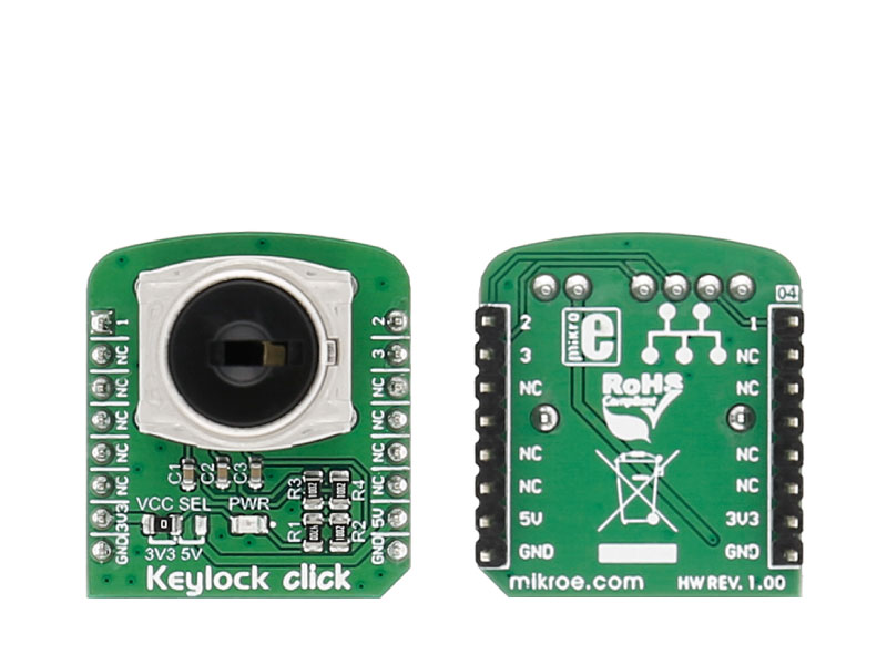
Keylock click carries a processed sealed key lock mechanism that can be set in three different positions. The click is designed to run on either 3.3V or 5V power supply. It communicates with the target microcontroller over the PWM, INT, and AN pin on the mikroBUSâ„¢ line.

No Abuse Reported

Do you want to subscribe in order to receive notifications regarding "Keylock click" changes.

Do you want to unsubscribe in order to stop receiving notifications regarding "Keylock click" changes.

Do you want to report abuse regarding "Keylock click".

  • mikroSDK Library 2.0.0.0
  • Comments (0)
DOWNLOAD LINK RELATED COMPILER CONTAINS
mikroBasic PRO for ARM
  • lib
  • src
  • exa
  • hlp
  • hex
  • sch
  • pcb
  • doc
mikroBasic PRO for AVR
  • lib
  • src
  • exa
  • hlp
  • hex
  • sch
  • pcb
  • doc
mikroBasic PRO for dsPIC30/33 & PIC24
  • lib
  • src
  • exa
  • hlp
  • hex
  • sch
  • pcb
  • doc
mikroBasic PRO for FT90x
  • lib
  • src
  • exa
  • hlp
  • hex
  • sch
  • pcb
  • doc
mikroBasic PRO for PIC
  • lib
  • src
  • exa
  • hlp
  • hex
  • sch
  • pcb
  • doc
mikroBasic PRO for PIC32
  • lib
  • src
  • exa
  • hlp
  • hex
  • sch
  • pcb
  • doc
mikroC PRO for ARM
  • lib
  • src
  • exa
  • hlp
  • hex
  • sch
  • pcb
  • doc
mikroC PRO for AVR
  • lib
  • src
  • exa
  • hlp
  • hex
  • sch
  • pcb
  • doc
mikroC PRO for dsPIC30/33 & PIC24
  • lib
  • src
  • exa
  • hlp
  • hex
  • sch
  • pcb
  • doc
mikroC PRO for FT90x
  • lib
  • src
  • exa
  • hlp
  • hex
  • sch
  • pcb
  • doc
mikroC PRO for PIC
  • lib
  • src
  • exa
  • hlp
  • hex
  • sch
  • pcb
  • doc
mikroC PRO for PIC32
  • lib
  • src
  • exa
  • hlp
  • hex
  • sch
  • pcb
  • doc
mikroPascal PRO for ARM
  • lib
  • src
  • exa
  • hlp
  • hex
  • sch
  • pcb
  • doc
mikroPascal PRO for AVR
  • lib
  • src
  • exa
  • hlp
  • hex
  • sch
  • pcb
  • doc
mikroPascal PRO for dsPIC30/33 & PIC24
  • lib
  • src
  • exa
  • hlp
  • hex
  • sch
  • pcb
  • doc
mikroPascal PRO for FT90x
  • lib
  • src
  • exa
  • hlp
  • hex
  • sch
  • pcb
  • doc
mikroPascal PRO for PIC
  • lib
  • src
  • exa
  • hlp
  • hex
  • sch
  • pcb
  • doc
mikroPascal PRO for PIC32
  • lib
  • src
  • exa
  • hlp
  • hex
  • sch
  • pcb
  • doc

mikroSDK Library Blog

Keylock click

Keylock click

Front and back view of the Keylock click board.

View full image

Library Description

The library covers all the functions necessary to control Keylock click board. Keylock click
communicates with the target board through the AN, PWM and INT line. This library 
offers functions for detecting the state in which the key currently is, as well as fuctions
that allow you to check the state of each of the pins used by Keylock click board.

Key functions:

  • uint8_t keylock_checkPin( uint8_t pin ); - Function is used to check the state of the pin chosen by the user.
  • uint8_t keylock_getPosition();- Function is used to check in which position the key currently is.

Examples description

The application is composed of three sections:

  • System Initialization - Initializes GPIO and LOG structures, sets AN, PWM and INT pins as output.
  • Application Initialization -  Initialization driver enables GPIO and also starts write log.
  • Application Task - (code snippet) This example demonstrates the use of Keylock Click board.
         Detects the position in which the key currently is. Results are being sent to the Usart Terminal,
         where you can track changes.
void applicationTask() 
{
    newState = keylock_getPosition();

    if( oldState != newState )
    {
        if( newState == _KEYLOCK_KEY_POS_1 )
        {
            mikrobus_logWrite( " Position ONE ", _LOG_LINE );
        }
            else if( newState == _KEYLOCK_KEY_POS_2 )
        {
            mikrobus_logWrite( " Position TWO ", _LOG_LINE );
        }

            else if( newState == _KEYLOCK_KEY_POS_3 )
        {
            mikrobus_logWrite( " Position THREE ", _LOG_LINE );
        }
        else
        {
            mikrobus_logWrite( " ERROR!!! ", _LOG_LINE );
        }
    oldState = newState;
    mikrobus_logWrite( "---------------", _LOG_LINE );
    }
    
    Delay_ms( 500 );
}  

Other mikroE Libraries used in the example:

  • UART

Additional notes and informations

Depending on the development board you are using, you may need USB UART clickUSB UART 2 click or RS232 click to connect to your PC, for development systems with no UART to USB interface available on the board. The terminal available in all MikroElektronika compilers, or any other terminal application of your choice, can be used to read the message

ALSO FROM THIS AUTHOR

Current 7 Click

0

Current 7 Click is a compact add-on board providing a precise and accurate current sensing solution. This board features the INA282, a wide common-mode range, bidirectional, high-accuracy current shunt monitor from Texas Instruments. The INA282 represents a voltage output current shunt monitor that can sense drops across shunts at common-mode voltages from –14 V to +80 V, independent of the supply voltage, which operates in a range from 2.7V up to 18V supply. The zero-drift topology enables high-precision measurements with maximum input offset voltages as low as 70μV. Also, the user is allowed to process the output signal in analog or digital form.

[Learn More]

ISO ADC 2 Click

0

ISO ADC 2 Click is a compact add-on board that represents a completely isolated 12-bit, 300 kSPS data acquisition system. This board features the AD7091R, successive-approximation analog-to-digital converter (ADC) from Analog Devices.

[Learn More]

Mikromedia 3 for TIVA Capacitive

0

This project contains demo example for Mikromedia 3 for TIVA Capacitive.

[Learn More]