TOP Contributors

  1. MIKROE (2662 codes)
  2. Alcides Ramos (357 codes)
  3. Shawon Shahryiar (307 codes)
  4. jm_palomino (112 codes)
  5. Chisanga Mumba (90 codes)
  6. S P (73 codes)
  7. dany (71 codes)
  8. MikroBUS.NET Team (35 codes)
  9. NART SCHINACKOW (34 codes)
  10. Armstrong Subero (27 codes)

Most Downloaded

  1. Timer Calculator (137038 times)
  2. FAT32 Library (70167 times)
  3. Network Ethernet Library (56039 times)
  4. USB Device Library (46364 times)
  5. Network WiFi Library (41980 times)
  6. FT800 Library (41310 times)
  7. GSM click (29079 times)
  8. mikroSDK (26519 times)
  9. PID Library (26453 times)
  10. microSD click (25449 times)
Libstock prefers package manager

Package Manager

We strongly encourage users to use Package manager for sharing their code on Libstock website, because it boosts your efficiency and leaves the end user with no room for error. [more info]

< Back
mikroSDK Library

OPTO 2 click

Rating:

5

Author: MIKROE

Last Updated: 2018-05-14

Package Version: 1.0.0.0

mikroSDK Library: 1.0.0.0

Category: Optocoupler

Downloaded: 3876 times

Not followed.

License: MIT license  

Opto 2 click is an optical isolator used to provide an optical galvanic isolation of sensitive lines.

No Abuse Reported

Do you want to subscribe in order to receive notifications regarding "OPTO 2 click" changes.

Do you want to unsubscribe in order to stop receiving notifications regarding "OPTO 2 click" changes.

Do you want to report abuse regarding "OPTO 2 click".
  • mikroSDK Library 2.0.0.0
  • Comments (0)
DOWNLOAD LINK RELATED COMPILER CONTAINS
mikroBasic PRO for ARM
  • lib
  • src
  • exa
  • hlp
  • hex
  • sch
  • pcb
  • doc
mikroBasic PRO for AVR
  • lib
  • src
  • exa
  • hlp
  • hex
  • sch
  • pcb
  • doc
mikroBasic PRO for dsPIC30/33 & PIC24
  • lib
  • src
  • exa
  • hlp
  • hex
  • sch
  • pcb
  • doc
mikroBasic PRO for FT90x
  • lib
  • src
  • exa
  • hlp
  • hex
  • sch
  • pcb
  • doc
mikroBasic PRO for PIC
  • lib
  • src
  • exa
  • hlp
  • hex
  • sch
  • pcb
  • doc
mikroBasic PRO for PIC32
  • lib
  • src
  • exa
  • hlp
  • hex
  • sch
  • pcb
  • doc
mikroC PRO for ARM
  • lib
  • src
  • exa
  • hlp
  • hex
  • sch
  • pcb
  • doc
mikroC PRO for AVR
  • lib
  • src
  • exa
  • hlp
  • hex
  • sch
  • pcb
  • doc
mikroC PRO for dsPIC30/33 & PIC24
  • lib
  • src
  • exa
  • hlp
  • hex
  • sch
  • pcb
  • doc
mikroC PRO for FT90x
  • lib
  • src
  • exa
  • hlp
  • hex
  • sch
  • pcb
  • doc
mikroC PRO for PIC
  • lib
  • src
  • exa
  • hlp
  • hex
  • sch
  • pcb
  • doc
mikroC PRO for PIC32
  • lib
  • src
  • exa
  • hlp
  • hex
  • sch
  • pcb
  • doc
mikroPascal PRO for ARM
  • lib
  • src
  • exa
  • hlp
  • hex
  • sch
  • pcb
  • doc
mikroPascal PRO for AVR
  • lib
  • src
  • exa
  • hlp
  • hex
  • sch
  • pcb
  • doc
mikroPascal PRO for dsPIC30/33 & PIC24
  • lib
  • src
  • exa
  • hlp
  • hex
  • sch
  • pcb
  • doc
mikroPascal PRO for FT90x
  • lib
  • src
  • exa
  • hlp
  • hex
  • sch
  • pcb
  • doc
mikroPascal PRO for PIC
  • lib
  • src
  • exa
  • hlp
  • hex
  • sch
  • pcb
  • doc
mikroPascal PRO for PIC32
  • lib
  • src
  • exa
  • hlp
  • hex
  • sch
  • pcb
  • doc

mikroSDK Library Blog

Opto 2 click

Opto 2 click

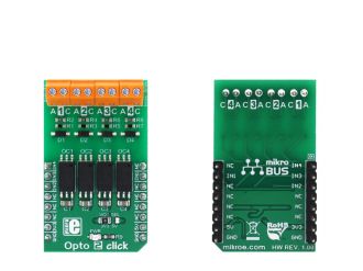
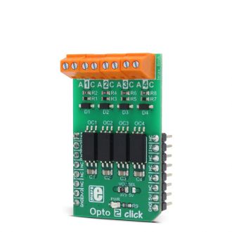
Native view of the Opto 2 click board.

View full image
Opto 2 click

Opto 2 click

Front and back view of the Opto 2 click board.

View full image

Library Description

The library performs the check procedure for the desired outputs (OUT1 - OUT4). For more details check the documentation.

Key functions:

  • uint8_t opto2_checkOut1( void ) - The function checks the state of the OUT1 pin.

Examples Description

The demo application is composed of three sections:

  • System Initialization - Initializes peripherals and pins.
  • Application Initialization -  Initializes GPIO driver and selects the outputs (OUT1 - OUT4) which state be checked.
  • Application Task - (code snippet) - Performs the check procedure for selected outputs and logs the states from the outputs on USB UART. Repeats the check procedure every 2 seconds.
     
void applicationTask()
{
 tmp = 1;

 for (cnt = 0; cnt < 4; cnt++)
 {
 switch (selOutput & tmp)
 {
 case 0x01 :
 {
 checkOutput = opto2_checkOut1();

 if (checkOutput == 0)
 {
 mikrobus_logWrite( "OUT1 is low", _LOG_LINE );
 }
 else
 {
 mikrobus_logWrite( "OUT1 is high", _LOG_LINE );
 }
 break;
 }
 case 0x02 :
 {
 checkOutput = opto2_checkOut2();

 if (checkOutput == 0)
 {
 mikrobus_logWrite( "OUT2 is low", _LOG_LINE );
 }
 else
 {
 mikrobus_logWrite( "OUT2 is high", _LOG_LINE );
 }
 break;
 }
 case 0x04 :
 {
 checkOutput = opto2_checkOut3();

 if (checkOutput == 0)
 {
 mikrobus_logWrite( "OUT3 is low", _LOG_LINE );
 }
 else
 {
 mikrobus_logWrite( "OUT3 is high", _LOG_LINE );
 }
 break;
 }
 case 0x08 :
 {
 checkOutput = opto2_checkOut4();

 if (checkOutput == 0)
 {
 mikrobus_logWrite( "OUT4 is low", _LOG_LINE );
 }
 else
 {
 mikrobus_logWrite( "OUT4 is high", _LOG_LINE );
 }
 break;
 }
 default :
 {
 break;
 }
 }

 tmp <<= 1;
 }
 mikrobus_logWrite( "", _LOG_LINE );

 Delay_ms( 2000 );
}
  • void opto2_setLogger( uint8_t selOut1, uint8_t selOut2, uint8_t selOut3, uint8_t selOut4 ) - Determines the outputs that be checked and logged on USB UART terminal. If selOutx is 1, the corresponding output will be included in check procedure.vAnd if selOutx is 0, that output will not be included in check procedure and will not be logged on UART.

mikroE Libraries used in the example:

  • UART

Additional notes and information

Depending on the development board you are using, you may need USB UART click,  USB UART 2 click or  RS232 click to connect to your PC, for development systems with no UART to USB interface available on the board. The terminal available in all MikroElektronika compilers, or any other terminal application of your choice, can be used to read the message.

ALSO FROM THIS AUTHOR

ADC3 Click

7

ADC3 click carries Microchip’s MCP3428 16-bit multichannel analog-to-digital converter. The click has four pairs of screw terminals onboard, letting you access the chip’s four differential input channels. ADC3 click communicates with the target MCU through mikroBUS I2C pins (SCL, SDA). It is designed to use either a 3.3V or 5V power supply.

[Learn More]

eFuse click

0

Fuse Click is a compact add-on board that contains a programmable electronic power breaker. This board features the STPW12, an integrated electronic power breaker optimized to monitor the input power from STMicroelectronics. Connected in series to the power rail, it can disconnect the electronic circuitry on its output if the power consumption overcomes the programmed limit. The intervention of the protection is communicated to the MCU through a signal on the fault pin. The device can also be enabled/disabled through a dedicated Enable pin with a direct PWM mode, which can be achieved through an external PWM signal.

[Learn More]

Gyro 9 click

0

Gyro 9 Click is a compact add-on board that contains a high-performance gyroscope. This board features the A3G4250D, a MEMS motion sensor from STMicroelectronics. It is a low-power 3-axes digital output gyroscope that provides unprecedented stability at zero rate level and sensitivity over temperature and time and is equipped with an embedded temperature sensor. The gyroscope has a 16-bit rate value data output with an 8-bit compensation temperature data output.

[Learn More]