TOP Contributors

  1. MIKROE (2784 codes)
  2. Alcides Ramos (405 codes)
  3. Shawon Shahryiar (307 codes)
  4. jm_palomino (133 codes)
  5. Bugz Bensce (97 codes)
  6. S P (73 codes)
  7. dany (71 codes)
  8. MikroBUS.NET Team (35 codes)
  9. NART SCHINACKOW (34 codes)
  10. Armstrong Subero (27 codes)

Most Downloaded

  1. Timer Calculator (141688 times)
  2. FAT32 Library (74758 times)
  3. Network Ethernet Library (59208 times)
  4. USB Device Library (49224 times)
  5. Network WiFi Library (44996 times)
  6. FT800 Library (44525 times)
  7. GSM click (31196 times)
  8. mikroSDK (30096 times)
  9. microSD click (27580 times)
  10. PID Library (27537 times)
Libstock prefers package manager

Package Manager

We strongly encourage users to use Package manager for sharing their code on Libstock website, because it boosts your efficiency and leaves the end user with no room for error. [more info]

< Back
mikroSDK Library

RS485 3.3V click

Rating:

0

Author: MIKROE

Last Updated: 2018-08-16

Package Version: 1.0.0.1

mikroSDK Library: 1.0.0.0

Category: RS485

Downloaded: 14431 times

Followed by: 2 users

License: MIT license  

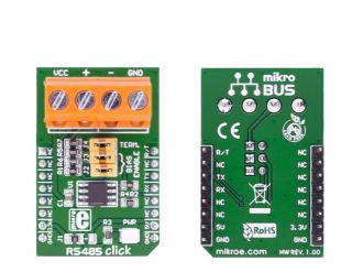
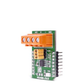
RS485 click 3.3V is a RS422/485 transceiver Click board, which can be used as an interface between the TTL level UART and the RS422/485 communication bus.

No Abuse Reported

Do you want to subscribe in order to receive notifications regarding "RS485 3.3V click " changes.

Do you want to unsubscribe in order to stop receiving notifications regarding "RS485 3.3V click " changes.

Do you want to report abuse regarding "RS485 3.3V click ".
  • mikroSDK Library 2.0.0.0
  • Comments (1)
DOWNLOAD LINK RELATED COMPILER CONTAINS
mikroBasic PRO for ARM
  • lib
  • src
  • exa
  • hlp
  • hex
  • sch
  • pcb
  • doc
mikroBasic PRO for AVR
  • lib
  • src
  • exa
  • hlp
  • hex
  • sch
  • pcb
  • doc
mikroBasic PRO for dsPIC30/33 & PIC24
  • lib
  • src
  • exa
  • hlp
  • hex
  • sch
  • pcb
  • doc
mikroBasic PRO for FT90x
  • lib
  • src
  • exa
  • hlp
  • hex
  • sch
  • pcb
  • doc
mikroBasic PRO for PIC
  • lib
  • src
  • exa
  • hlp
  • hex
  • sch
  • pcb
  • doc
mikroBasic PRO for PIC32
  • lib
  • src
  • exa
  • hlp
  • hex
  • sch
  • pcb
  • doc
mikroC PRO for ARM
  • lib
  • src
  • exa
  • hlp
  • hex
  • sch
  • pcb
  • doc
mikroC PRO for AVR
  • lib
  • src
  • exa
  • hlp
  • hex
  • sch
  • pcb
  • doc
mikroC PRO for dsPIC30/33 & PIC24
  • lib
  • src
  • exa
  • hlp
  • hex
  • sch
  • pcb
  • doc
mikroC PRO for FT90x
  • lib
  • src
  • exa
  • hlp
  • hex
  • sch
  • pcb
  • doc
mikroC PRO for PIC
  • lib
  • src
  • exa
  • hlp
  • hex
  • sch
  • pcb
  • doc
mikroC PRO for PIC32
  • lib
  • src
  • exa
  • hlp
  • hex
  • sch
  • pcb
  • doc
mikroPascal PRO for ARM
  • lib
  • src
  • exa
  • hlp
  • hex
  • sch
  • pcb
  • doc
mikroPascal PRO for AVR
  • lib
  • src
  • exa
  • hlp
  • hex
  • sch
  • pcb
  • doc
mikroPascal PRO for dsPIC30/33 & PIC24
  • lib
  • src
  • exa
  • hlp
  • hex
  • sch
  • pcb
  • doc
mikroPascal PRO for FT90x
  • lib
  • src
  • exa
  • hlp
  • hex
  • sch
  • pcb
  • doc
mikroPascal PRO for PIC
  • lib
  • src
  • exa
  • hlp
  • hex
  • sch
  • pcb
  • doc
mikroPascal PRO for PIC32
  • lib
  • src
  • exa
  • hlp
  • hex
  • sch
  • pcb
  • doc

mikroSDK Library Blog

RS485 3v3 click

RS485 3v3 click

Native view of the RS485 3v3 click board.

View full image
RS485 3v3 click

RS485 3v3 click

Front and back view of the RS485 3v3 click board.

View full image

Library Description

Library initializes and defines GPIO driver and performs control of device voltage.
For more details check the documentation.

Key functions:

  • void rs485_writeByte(uint8_t input)  - Write Single Byte.
  • uint8_t rs485_readByte() - Read Single Byte.
  • uint8_t ras485_byteReady() - Check for new byte received.

Example description

The application is composed of three sections:

  • System Initialization -  Initializes UART module.
  • Application Initialization -  Driver intialization.
  • Application Task - (code snippet) - Checks if new data byte has been received in the RX buffer (ready for reading), and if it has then it reads one byte from the RX buffer. Otherwise, the application task writes the message data via UART.
void applicationTask()
{
 char tmp;
 uint8_t rdyFlag;

// RECEIVER - UART polling 

 rdyFlag = rs485_byteReady();

 if (1 == rdyFlag)
 {
 tmp = rs485_readByte();
 mikrobus_logWrite( &tmp, _LOG_BYTE );
 }

// TRANSMITER - TX each 2 sec
/*
 for (tmp = 0; tmp < 9; tmp++)
 {
 rs485_writeByte( MESSAGE_DATA[tmp] );
 mikrobus_logWrite( "MESSAGE SENT", _LOG_LINE );
 }
 Delay_ms(2000);
*/

}

Other mikroE Libraries used in this example:

  • UART

Additional notes and information

Depending on the development board you are using, you may need USB UART click,  USB UART 2 click or  RS232 click to connect to your PC, for development systems with no UART to USB interface available on the board. The terminal available in all MikroElektronika compilers, or any other terminal application of your choice, can be used to read the message.

ALSO FROM THIS AUTHOR

BLE TX Click

0

BLE TX Click is a compact add-on board that contains a low-energy Bluetooth transmitter. This board features the AK1595, a Bluetooth 5.2 transmitter with incorporated proprietary algorithm software from AKM Semiconductor. The AK1595 transmitter simplifies wireless connectivity to a system with no need to develop complicated, proprietary microcontroller code. Bluetooth Low Energy compliant advertising transmission can be achieved by simply configuring the transmission power, data, and transmission start-trigger via the UART or I2C interface.

[Learn More]

Signal Relay Click

0

Signal Relay Click can be used for ON/OFF control in various devices. It carries four ultra-small GV5-1 PCB relays from Omron and runs on a 5V power supply.

[Learn More]

N-PLC Click

0

N-PLC Click is a compact add-on board that uses existing electrical power lines to transmit data signals. This board features the SM2400, an advanced multi-standard Narrow-band Power Line Communication (N-PLC) modem from Semitech. The SM2400 features a dual-core architecture, a DSP core for N-PLC modulations, and a 32-bit core for running protocols for superior communication performance and flexibility for various open standards and customized implementations. It includes firmware options for IEEE 1901.2 compliant PHY and MAC layers, a 6LoWPAN data link layer, and special modes for industrial IoT applications. In addition to the ability to accept signals from another PLC modem or the power line communication AC coupling circuit, this board also has a handful of other features, such as a selectable interface and power supply, firmware update capabilities, LED indicators, and many others.

[Learn More]