TOP Contributors

  1. MIKROE (2663 codes)
  2. Alcides Ramos (358 codes)
  3. Shawon Shahryiar (307 codes)
  4. jm_palomino (112 codes)
  5. Chisanga Mumba (90 codes)
  6. S P (73 codes)
  7. dany (71 codes)
  8. MikroBUS.NET Team (35 codes)
  9. NART SCHINACKOW (34 codes)
  10. Armstrong Subero (27 codes)

Most Downloaded

  1. Timer Calculator (137083 times)
  2. FAT32 Library (70224 times)
  3. Network Ethernet Library (56097 times)
  4. USB Device Library (46424 times)
  5. Network WiFi Library (42040 times)
  6. FT800 Library (41381 times)
  7. GSM click (29109 times)
  8. mikroSDK (26558 times)
  9. PID Library (26487 times)
  10. microSD click (25486 times)
Libstock prefers package manager

Package Manager

We strongly encourage users to use Package manager for sharing their code on Libstock website, because it boosts your efficiency and leaves the end user with no room for error. [more info]

< Back
mikroSDK Library

Smart Buck click

Rating:

5

Author: MIKROE

Last Updated: 2018-09-04

Package Version: 1.0.0.0

mikroSDK Library: 1.0.0.0

Category: Buck

Downloaded: 3653 times

Not followed.

License: MIT license  

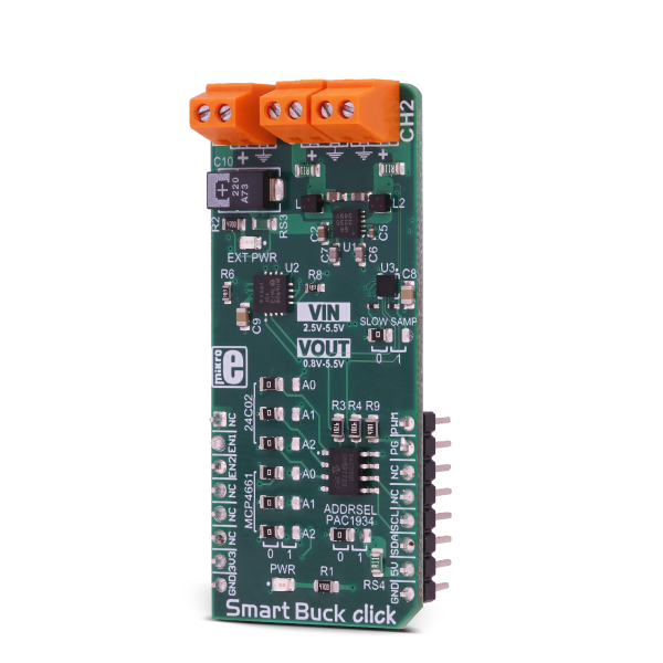
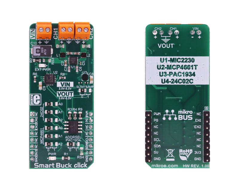
Smart Buck click is the two-channel step-down DC/DC converter and regulator, with plenty of additional functions. It can provide voltage measurement at each of its two programmable voltage outputs, as well as the measurement of the current consumption.

No Abuse Reported

Do you want to subscribe in order to receive notifications regarding "Smart Buck click" changes.

Do you want to unsubscribe in order to stop receiving notifications regarding "Smart Buck click" changes.

Do you want to report abuse regarding "Smart Buck click".

  • mikroSDK Library 2.0.0.0
  • Comments (0)
DOWNLOAD LINK RELATED COMPILER CONTAINS
mikroBasic PRO for ARM
  • lib
  • src
  • exa
  • hlp
  • hex
  • sch
  • pcb
  • doc
mikroBasic PRO for AVR
  • lib
  • src
  • exa
  • hlp
  • hex
  • sch
  • pcb
  • doc
mikroBasic PRO for dsPIC30/33 & PIC24
  • lib
  • src
  • exa
  • hlp
  • hex
  • sch
  • pcb
  • doc
mikroBasic PRO for FT90x
  • lib
  • src
  • exa
  • hlp
  • hex
  • sch
  • pcb
  • doc
mikroBasic PRO for PIC
  • lib
  • src
  • exa
  • hlp
  • hex
  • sch
  • pcb
  • doc
mikroBasic PRO for PIC32
  • lib
  • src
  • exa
  • hlp
  • hex
  • sch
  • pcb
  • doc
mikroC PRO for ARM
  • lib
  • src
  • exa
  • hlp
  • hex
  • sch
  • pcb
  • doc
mikroC PRO for AVR
  • lib
  • src
  • exa
  • hlp
  • hex
  • sch
  • pcb
  • doc
mikroC PRO for dsPIC30/33 & PIC24
  • lib
  • src
  • exa
  • hlp
  • hex
  • sch
  • pcb
  • doc
mikroC PRO for FT90x
  • lib
  • src
  • exa
  • hlp
  • hex
  • sch
  • pcb
  • doc
mikroC PRO for PIC
  • lib
  • src
  • exa
  • hlp
  • hex
  • sch
  • pcb
  • doc
mikroC PRO for PIC32
  • lib
  • src
  • exa
  • hlp
  • hex
  • sch
  • pcb
  • doc
mikroPascal PRO for ARM
  • lib
  • src
  • exa
  • hlp
  • hex
  • sch
  • pcb
  • doc
mikroPascal PRO for AVR
  • lib
  • src
  • exa
  • hlp
  • hex
  • sch
  • pcb
  • doc
mikroPascal PRO for dsPIC30/33 & PIC24
  • lib
  • src
  • exa
  • hlp
  • hex
  • sch
  • pcb
  • doc
mikroPascal PRO for FT90x
  • lib
  • src
  • exa
  • hlp
  • hex
  • sch
  • pcb
  • doc
mikroPascal PRO for PIC
  • lib
  • src
  • exa
  • hlp
  • hex
  • sch
  • pcb
  • doc
mikroPascal PRO for PIC32
  • lib
  • src
  • exa
  • hlp
  • hex
  • sch
  • pcb
  • doc

mikroSDK Library Blog

Smart Buck click

Smart Buck click

Native view of the Smart Buck click board.

View full image
Smart Buck click

Smart Buck click

Front and back view of the Smart Buck click board.

View full image

Library Description

Library offers a choice to communicate with all devices on Smart Buck click. The library has the ability to control both regulators, both wipers on the potentiometer, EEPROM memory and main sense chip (PAC1934). User can get from driver functions voltage(V), current(mA) and power(mW) data for each activated channel on click. The user also can perform desired configurations, that includes a number of activated channels, data format (unsigned or signed) for each channel, and data selection, which determines a configuration for conversion cycle, one sample data or more samples (averaged data) will be converted in one conversion cycle. For more details check the documentation.

Key functions:

  • uint8_t smartbuck_writePot( uint8_t regAddr, uint16_t dataIn ) - The function writes 16bit data to the Potentiometer register (MCP4661).
  • void smartbuck_enRegulator1( uint8_t state ) - Function puts Regulator1 to the desired state.
  • uint8_t smartbuck_setConfigPAC( uint8_t enChann, uint8_t dataFormat, uint8_t dataSel ) - The function sets configuration for conversion cycle for PAC1934.
  • void smartbuck_getData( float *voltage, float *current, float *power ) - The function reads and calculates the voltage, current and power data from PAC1934 activated channels.

Example description

The application is composed of three sections:

  • System Initialization -   Initializes peripherals and pins.
  • Application Initialization - Initializes I2C interface and performs the click configuration to work in Single-Shot Mode with signed averaged data of 64 samples. CH1 and CH3 are only activated and included in the conversion cycle.
  • Application Task - (code snippet) - Sends command to update data registers with newly converted data, waits one second and after that reads new data from data registers. In this way, a user can get voltage, current and power data for activated channels. Results for activated channels logs on UART terminal. Note: If we want to update registers with new converted data, after at least one conversion cycle is done, we should send first REFRESH or REFRESH_V command, before data be read, which will update registers with new values. Also, these commands will update the Control register with new desired configurations.
void applicationTask()
{
 smartbuck_sendCmdPAC( _SMARTBUCK_REFRESH_V_CMND );
 Delay_ms( 1000 );
 smartbuck_getData( &voltageRes[0], ¤tRes[0], &powerRes[0] );

 checkByte = 0x80;
 index = 0;

 for (cnt = 0; cnt < 4; cnt++)
 {
 if ((enabledChann & checkByte) == 0)
 {
 channelLog();

 FloatToStr( voltageRes[ index ], text );
 mikrobus_logWrite( text, _LOG_TEXT );
 mikrobus_logWrite( "V", _LOG_LINE );

 FloatToStr( currentRes[ index ], text );
 mikrobus_logWrite( text, _LOG_TEXT );
 mikrobus_logWrite( "mA", _LOG_LINE );

 FloatToStr( powerRes[ index ], text );
 mikrobus_logWrite( text, _LOG_TEXT );
 mikrobus_logWrite( "mW", _LOG_LINE );

 index++;
 }
 checkByte >>= 1;
 }

 mikrobus_logWrite( "", _LOG_LINE );
}

Additional Functions :

  • channelLog - Checks which channel is activated (from CH1 to CH4) and logs text on UART.


Other MikroElektronika libraries used in the example:

  • Conversions
  • I2C
  • UART

Additional notes and information

Depending on the development board you are using, you may need USB UART clickUSB UART 2 click or RS232 click to connect to your PC, for development systems with no UART to USB interface available on the board. The terminal available in all MikroElektronika compilers, or any other terminal application of your choice, can be used to read the message.

ALSO FROM THIS AUTHOR

DAC 9 click

0

DAC 9 Click is a compact add-on board that contains a fully-featured, highly accurate digital-to-analog converter. This board features the DAC80501, a 16-bit voltage-output digital-to-analog converter with precision internal reference from Texas Instruments. It supports both I2C and SPI serial interface and offers a linearity of < 1 LSB. It also includes a 2.5V internal reference, giving full-scale output voltage ranges of 1.25V, 2.5V, or 5V, incorporate a Power-On Reset function, consume a low current of 1mA, and include a Power-Down feature that reduces current consumption to typically 15μA at 5V.

[Learn More]

Buck 11 click

5

Buck 11 click is a high-efficiency step-down converter which provides 3.3V on its output, derived from the connected power supply voltage, in the range from 4.2V to 60V.

[Learn More]

NB IoT click

0

NB IoT click is a Click board™ that allows LTE Cat NB1 connectivity by utilizing Quectel BC95-G, a specialized multi-band IoT module with very low power requirements and compact form factor, making it perfectly suited for various IoT-based applications.

[Learn More]