TOP Contributors

  1. MIKROE (2663 codes)
  2. Alcides Ramos (358 codes)
  3. Shawon Shahryiar (307 codes)
  4. jm_palomino (112 codes)
  5. Chisanga Mumba (90 codes)
  6. S P (73 codes)
  7. dany (71 codes)
  8. MikroBUS.NET Team (35 codes)
  9. NART SCHINACKOW (34 codes)
  10. Armstrong Subero (27 codes)

Most Downloaded

  1. Timer Calculator (137081 times)
  2. FAT32 Library (70223 times)
  3. Network Ethernet Library (56095 times)
  4. USB Device Library (46418 times)
  5. Network WiFi Library (42032 times)
  6. FT800 Library (41378 times)
  7. GSM click (29109 times)
  8. mikroSDK (26557 times)
  9. PID Library (26487 times)
  10. microSD click (25486 times)
Libstock prefers package manager

Package Manager

We strongly encourage users to use Package manager for sharing their code on Libstock website, because it boosts your efficiency and leaves the end user with no room for error. [more info]

< Back
mikroSDK Library

Waveform click

Rating:

5

Author: MIKROE

Last Updated: 2021-10-04

Package Version: 1.0.0.0

mikroSDK Library: 1.0.0.0

Category: Clock generator

Downloaded: 4508 times

Not followed.

License: MIT license  

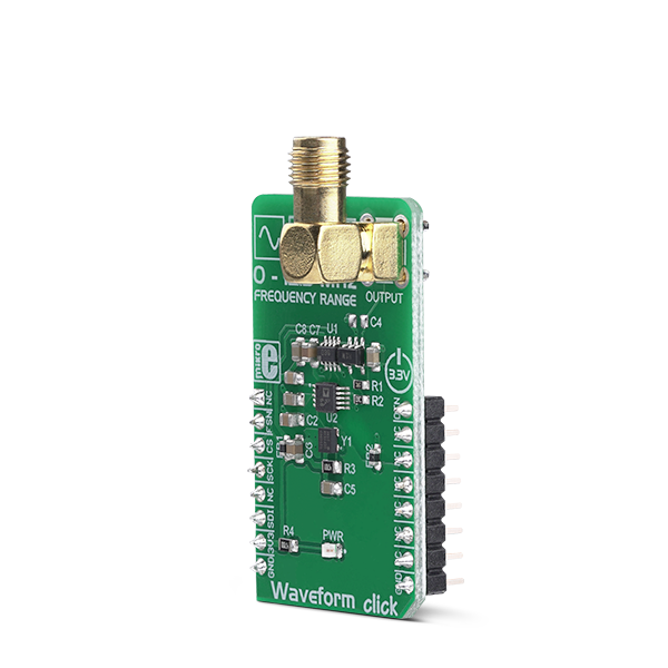
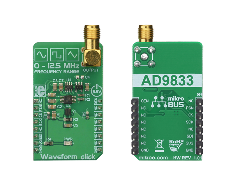
Waveform Click is a precise sine/triangle/square waveform generator, capable of reproducing frequencies up to 12MHz.

No Abuse Reported

Do you want to subscribe in order to receive notifications regarding "Waveform click" changes.

Do you want to unsubscribe in order to stop receiving notifications regarding "Waveform click" changes.

Do you want to report abuse regarding "Waveform click".

  • mikroSDK Library 2.0.0.0
  • Comments (0)
DOWNLOAD LINK RELATED COMPILER CONTAINS
mikroBasic PRO for ARM
  • lib
  • src
  • exa
  • hlp
  • hex
  • sch
  • pcb
  • doc
mikroBasic PRO for AVR
  • lib
  • src
  • exa
  • hlp
  • hex
  • sch
  • pcb
  • doc
mikroBasic PRO for dsPIC30/33 & PIC24
  • lib
  • src
  • exa
  • hlp
  • hex
  • sch
  • pcb
  • doc
mikroBasic PRO for FT90x
  • lib
  • src
  • exa
  • hlp
  • hex
  • sch
  • pcb
  • doc
mikroBasic PRO for PIC
  • lib
  • src
  • exa
  • hlp
  • hex
  • sch
  • pcb
  • doc
mikroBasic PRO for PIC32
  • lib
  • src
  • exa
  • hlp
  • hex
  • sch
  • pcb
  • doc
mikroC PRO for ARM
  • lib
  • src
  • exa
  • hlp
  • hex
  • sch
  • pcb
  • doc
mikroC PRO for AVR
  • lib
  • src
  • exa
  • hlp
  • hex
  • sch
  • pcb
  • doc
mikroC PRO for dsPIC30/33 & PIC24
  • lib
  • src
  • exa
  • hlp
  • hex
  • sch
  • pcb
  • doc
mikroC PRO for FT90x
  • lib
  • src
  • exa
  • hlp
  • hex
  • sch
  • pcb
  • doc
mikroC PRO for PIC
  • lib
  • src
  • exa
  • hlp
  • hex
  • sch
  • pcb
  • doc
mikroC PRO for PIC32
  • lib
  • src
  • exa
  • hlp
  • hex
  • sch
  • pcb
  • doc
mikroPascal PRO for ARM
  • lib
  • src
  • exa
  • hlp
  • hex
  • sch
  • pcb
  • doc
mikroPascal PRO for AVR
  • lib
  • src
  • exa
  • hlp
  • hex
  • sch
  • pcb
  • doc
mikroPascal PRO for dsPIC30/33 & PIC24
  • lib
  • src
  • exa
  • hlp
  • hex
  • sch
  • pcb
  • doc
mikroPascal PRO for FT90x
  • lib
  • src
  • exa
  • hlp
  • hex
  • sch
  • pcb
  • doc
mikroPascal PRO for PIC
  • lib
  • src
  • exa
  • hlp
  • hex
  • sch
  • pcb
  • doc
mikroPascal PRO for PIC32
  • lib
  • src
  • exa
  • hlp
  • hex
  • sch
  • pcb
  • doc

mikroSDK Library Blog

Waveform Click

Waveform Click

Native view of the Waveform Click board.

View full image
Waveform Click

Waveform Click

Front and back view of the Waveform Click board.

View full image

Library Description

Library contains generic functions for controlling the waveform and frequency
output of the click board.

Key functions:

  • void waveform_sineOutput(uint32_t f) - Function for setting the sine wave output.
  • void waveform_triangleOutput(uint32_t f) - Function for setting the triangle wave output.
  • void waveform_squareOutput(uint32_t f) - Function for setting the square wave output.

Examples description

The application is composed of the three sections :

  • System Initialization - Initialize the GPIO and communication structures.
  • Application Initialization - Initialization driver init, default configuration and sets first volume.
  • Application Initialization - Initialize the communication interface and configure the click board.
  • Application Task - Predefined characters are inputed from the serial port. Depending on the character sent the signal frequency, waveform or amplitude will be changed.
void applicationTask()
{
    char rxDat;
    uint32_t freqTmp;
 
    if(UART_Rdy_Ptr())
    {
       rxDat = UART_Rd_Ptr();
       mikrobus_logWrite(&rxDat,_LOG_BYTE);
    }
    if(rxDat>0)
    {
       switch(rxDat)
       {
           case waveform_cmd[0]: {
                                     waveform_digipotInc();
                                     rxDat = 0;
                                     break;
                                 }
           case waveform_cmd[1]: {
                                     waveform_digipotDec();
                                     rxDat = 0;
                                     break;
                                 }
           case waveform_cmd[2]: {
                                     freq += 1;
                                     freqTmp = freq << 14;
                                     waveform_sineOutput(freqTmp);
                                     rxDat = 0;
                                     break;
                                 }
           case waveform_cmd[3]: {
                                     freq -= 1;
                                     freqTmp = freq << 14;
                                     waveform_sineOutput(freqTmp);
                                     rxDat = 0;
                                     break;
                                 }
           case waveform_cmd[4]: {
                                     freq += 1;
                                     freqTmp = freq << 14;
                                     waveform_triangleOutput(freqTmp);
                                     rxDat = 0;
                                     break;
                                 }
           case waveform_cmd[5]: {
                                     freq -= 1;
                                     freqTmp = freq << 14;
                                     waveform_triangleOutput(freqTmp);
                                     rxDat = 0;
                                     break;
                                 }
           case waveform_cmd[6]: {
                                     freq += 1;
                                     freqTmp = freq << 14;
                                     waveform_squareOutput(freqTmp);
                                     rxDat = 0;
                                     break;
                                 }
           case waveform_cmd[7]: {
                                     freq -= 1;
                                     freqTmp = freq << 14;
                                     waveform_squareOutput(freqTmp);
                                     rxDat = 0;
                                     break;
                                 }
           default : {
                         break;
                     }
       }
    }
     rxDat = 0;
}

Additional Functions :

  • uint32_t waveform_aproxFreqcalculation(float freqency) - This function is used to calculate the aproximate value that will be written to the frequency set register.

Other mikroE Libraries used in the example:

  • SPI
  • UART
  • Conversions
  • C_Sring

Additional notes and informations

Depending on the development board you are using, you may need USB UART clickUSB UART 2 click or RS232 click to connect to your PC, for development systems with no UART to USB interface available on the board. The terminal available in all MikroElektronika compilers, or any other terminal application of your choice, can be used to read the message.

ALSO FROM THIS AUTHOR

PHT click

5

PHT Click is a compact add-on board that contains a PHT combo sensor. This board features the MS8607, a digital combination sensor providing 3 environmental measurements all-in-one: pressure, humidity, and temperature from TE Connectivity Measurement Specialties.

[Learn More]

H-Bridge click

0

H-Bridge click is a high-efficiency dual H-bridge driver Click board™, capable of providing reasonably high current while driving the connected load with up to 7V. Since the used driver IC has two full H-bridge channels, this Click board™ is an ideal solution for driving smaller bipolar stepper motors. H-Bridge click provides driving in both directions, with an addition of the brake mode, and the high impedance mode (Hi-Z). Overshoot current suppression algorithm protects the output stages from being damaged if both high-side and low-side MOSFETs on a single H-bridge channel become conductive.

[Learn More]

CAN FD 3 click

0

CAN FD 3 Click is a add-on board based on TLE9251V CAN network transceiver, designed for HS CAN networks up to 5 Mbit/s in automotive and industrial applications.

[Learn More]