TOP Contributors

  1. MIKROE (2784 codes)
  2. Alcides Ramos (405 codes)
  3. Shawon Shahryiar (307 codes)
  4. jm_palomino (133 codes)
  5. Bugz Bensce (97 codes)
  6. S P (73 codes)
  7. dany (71 codes)
  8. MikroBUS.NET Team (35 codes)
  9. NART SCHINACKOW (34 codes)
  10. Armstrong Subero (27 codes)

Most Downloaded

  1. Timer Calculator (142085 times)
  2. FAT32 Library (75308 times)
  3. Network Ethernet Library (59504 times)
  4. USB Device Library (49526 times)
  5. Network WiFi Library (45290 times)
  6. FT800 Library (44928 times)
  7. GSM click (31442 times)
  8. mikroSDK (30467 times)
  9. microSD click (27804 times)
  10. PID Library (27625 times)
Libstock prefers package manager

Package Manager

We strongly encourage users to use Package manager for sharing their code on Libstock website, because it boosts your efficiency and leaves the end user with no room for error. [more info]

< Back
mikroSDK Library

RFID 2 click

Rating:

5

Author: MIKROE

Last Updated: 2020-10-26

Package Version: 1.0.0.0

mikroSDK Library: 1.0.0.0

Category: RFid

Downloaded: 3988 times

Not followed.

License: MIT license  

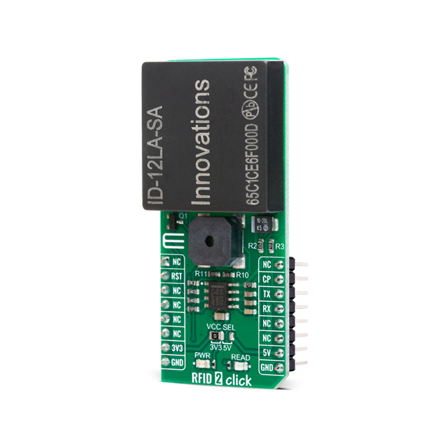
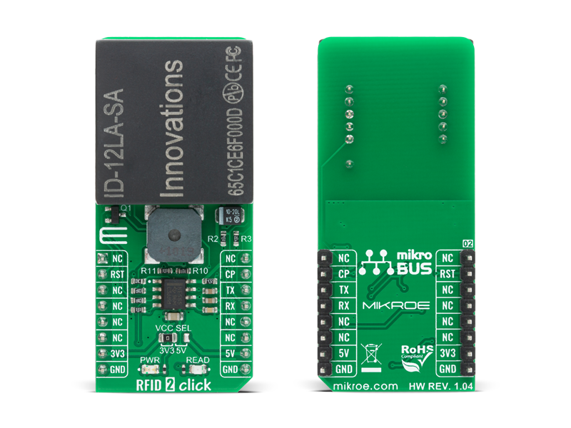
RFID 2 Click is a compact add-on board that contains a stand-alone RFID reader with a built-in antenna easy-to-use for embedded applications. This board features the ID-12LA-SA, an advanced low-cost RFID reader module usable with 38 different tags from ID Innovations.

No Abuse Reported

Do you want to subscribe in order to receive notifications regarding "RFID 2 click" changes.

Do you want to unsubscribe in order to stop receiving notifications regarding "RFID 2 click" changes.

Do you want to report abuse regarding "RFID 2 click".

  • mikroSDK Library 2.0.0.0
  • Comments (0)
DOWNLOAD LINK RELATED COMPILER CONTAINS
mikroBasic PRO for ARM
  • lib
  • src
  • exa
  • hlp
  • hex
  • sch
  • pcb
  • doc
mikroBasic PRO for AVR
  • lib
  • src
  • exa
  • hlp
  • hex
  • sch
  • pcb
  • doc
mikroBasic PRO for dsPIC30/33 & PIC24
  • lib
  • src
  • exa
  • hlp
  • hex
  • sch
  • pcb
  • doc
mikroBasic PRO for FT90x
  • lib
  • src
  • exa
  • hlp
  • hex
  • sch
  • pcb
  • doc
mikroBasic PRO for PIC
  • lib
  • src
  • exa
  • hlp
  • hex
  • sch
  • pcb
  • doc
mikroBasic PRO for PIC32
  • lib
  • src
  • exa
  • hlp
  • hex
  • sch
  • pcb
  • doc
mikroC PRO for ARM
  • lib
  • src
  • exa
  • hlp
  • hex
  • sch
  • pcb
  • doc
mikroC PRO for AVR
  • lib
  • src
  • exa
  • hlp
  • hex
  • sch
  • pcb
  • doc
mikroC PRO for dsPIC30/33 & PIC24
  • lib
  • src
  • exa
  • hlp
  • hex
  • sch
  • pcb
  • doc
mikroC PRO for FT90x
  • lib
  • src
  • exa
  • hlp
  • hex
  • sch
  • pcb
  • doc
mikroC PRO for PIC
  • lib
  • src
  • exa
  • hlp
  • hex
  • sch
  • pcb
  • doc
mikroC PRO for PIC32
  • lib
  • src
  • exa
  • hlp
  • hex
  • sch
  • pcb
  • doc
mikroPascal PRO for ARM
  • lib
  • src
  • exa
  • hlp
  • hex
  • sch
  • pcb
  • doc
mikroPascal PRO for AVR
  • lib
  • src
  • exa
  • hlp
  • hex
  • sch
  • pcb
  • doc
mikroPascal PRO for dsPIC30/33 & PIC24
  • lib
  • src
  • exa
  • hlp
  • hex
  • sch
  • pcb
  • doc
mikroPascal PRO for FT90x
  • lib
  • src
  • exa
  • hlp
  • hex
  • sch
  • pcb
  • doc
mikroPascal PRO for PIC
  • lib
  • src
  • exa
  • hlp
  • hex
  • sch
  • pcb
  • doc
mikroPascal PRO for PIC32
  • lib
  • src
  • exa
  • hlp
  • hex
  • sch
  • pcb
  • doc

mikroSDK Library Blog

RFID 2 Click

RFID 2 Click

Native view of the RFID 2 Click board.

View full image
RFID 2 Click

RFID 2 Click

Front and back view of the RFID 2 Click board.

View full image

Library Description

Initializes and defines UART bus driver, and defines driver's functions for comunication reading and writing. The library includes function for read ID (card / tag) in hex or dec value. The user also has the function for reset device and function for get interrupt pin state.

Key functions:

  • uint8_t rfid2_get_id_card( uint8_t *id_card ) - Function for get ID card
  • void rfid2_reset() - Function for reset device
  • uint32_t rfid2_hex_to_dec (char *id_hex) - Function for convert ID card [HEX] to ID card [DEC]

Examples description

The application is composed of three sections :

  • System Initialization - Initializes UART module and sets RST pin as OUTPUT and INT pin as INPUT
  • Application Initialization - Initializes Driver init and reset chip
  • Application Task - (code snippet) - Reads the ID card [HEX and DEC] and logs data on the USBUART-a.
void application_task ( )
{
    char id_card_hex[ 15 ] = { 0 };
    uint32_t id_card_dec;
    uint8_t card_error;
    char demo_text[ 20 ];

    memset( &id_card_hex, 0 , 15 );
    card_error = rfid2_get_id_card( &id_card_hex[ 0 ] );

    if ( card_error == RFID2_CARD_IS_SUCCESSFULLY_READ )
    {
        id_card_dec = rfid2_hex_to_dec( &id_card_hex[ 0 ] );
        mikrobus_logWrite( "* ID card(hex) is =  0x", _LOG_TEXT );
        mikrobus_logWrite( id_card_hex, _LOG_TEXT );
        mikrobus_logWrite( "* ID card(dec) is = ", _LOG_TEXT );
        LongWordToStr(id_card_dec, demo_text);
        mikrobus_logWrite( demo_text, _LOG_LINE );
        mikrobus_logWrite( "* Card is successfully read.", _LOG_LINE );
        mikrobus_logWrite( " ", _LOG_LINE );

        mikrobus_logWrite( ">>> Please, put your ID card. ", _LOG_LINE );
        Delay_ms( 100 );
    }
}

Other mikroE Libraries used in the example:

  • UART Library
  • Conversions Library

Additional notes and informations

Depending on the development board you are using, you may need USB UART clickUSB UART 2 click or RS232 click to connect to your PC, for development systems with no UART to USB interface available on the board. The terminal available in all MikroElektronika compilers, or any other terminal application of your choice, can be used to read the message.

ALSO FROM THIS AUTHOR

OLED B click

5

OLED B click carries a 96 x 39px blue monochrome passive matrix OLED display. The display is bright, has a wide viewing angle and low power consumption. To drive the display, OLED B click features an SSD1306 controller.

[Learn More]

V to Hz Click

0

V to HZ Click is a device that converts an analog voltage input signal into a pulse wave signal of a certain frequency. It has a linear response, so applying a voltage in a range of 0 to 5V on its input, will result in generating the pulse train with frequency linearly proportional to the input voltage.

[Learn More]

Multi Stepper TB67S109 Click

0

Multi Stepper Click is a compact add-on board that contains a bipolar stepper motor driver. This board features the TB67S109AFTG, CLOCK-in controlled bipolar stepping motor driver from Toshiba Semiconductor. It supports a PWM constant-current control drive and allows from full-step up to 1/32 steps resolution for less motor noise and smoother control. It has a wide operating voltage range of 10V to 47V with an output current capacity of 2.8A in addition to several built-in error detection circuits.

[Learn More]