TOP Contributors

  1. MIKROE (2784 codes)
  2. Alcides Ramos (405 codes)
  3. Shawon Shahryiar (307 codes)
  4. jm_palomino (133 codes)
  5. Bugz Bensce (97 codes)
  6. S P (73 codes)
  7. dany (71 codes)
  8. MikroBUS.NET Team (35 codes)
  9. NART SCHINACKOW (34 codes)
  10. Armstrong Subero (27 codes)

Most Downloaded

  1. Timer Calculator (141912 times)
  2. FAT32 Library (75058 times)
  3. Network Ethernet Library (59355 times)
  4. USB Device Library (49352 times)
  5. Network WiFi Library (45168 times)
  6. FT800 Library (44723 times)
  7. GSM click (31307 times)
  8. mikroSDK (30270 times)
  9. microSD click (27689 times)
  10. PID Library (27577 times)
Libstock prefers package manager

Package Manager

We strongly encourage users to use Package manager for sharing their code on Libstock website, because it boosts your efficiency and leaves the end user with no room for error. [more info]

< Back
mikroSDK Library

Relay 3 click

Rating:

10

Author: MIKROE

Last Updated: 2019-02-07

Package Version: 1.0.0.0

mikroSDK Library: 1.0.0.0

Category: Relay

Downloaded: 5440 times

Not followed.

License: MIT license  

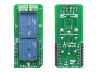
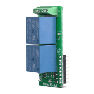
Relay click 3 is a dual relay Click board, featuring two single-pole double-throw relays which can be operated by output pins of the host microcontroller (MCU).

No Abuse Reported

Do you want to subscribe in order to receive notifications regarding "Relay 3 click" changes.

Do you want to unsubscribe in order to stop receiving notifications regarding "Relay 3 click" changes.

Do you want to report abuse regarding "Relay 3 click".
  • mikroSDK Library 2.0.0.0
  • Comments (0)
DOWNLOAD LINK RELATED COMPILER CONTAINS
mikroBasic PRO for ARM
  • lib
  • src
  • exa
  • hlp
  • hex
  • sch
  • pcb
  • doc
mikroBasic PRO for AVR
  • lib
  • src
  • exa
  • hlp
  • hex
  • sch
  • pcb
  • doc
mikroBasic PRO for dsPIC30/33 & PIC24
  • lib
  • src
  • exa
  • hlp
  • hex
  • sch
  • pcb
  • doc
mikroBasic PRO for FT90x
  • lib
  • src
  • exa
  • hlp
  • hex
  • sch
  • pcb
  • doc
mikroBasic PRO for PIC
  • lib
  • src
  • exa
  • hlp
  • hex
  • sch
  • pcb
  • doc
mikroBasic PRO for PIC32
  • lib
  • src
  • exa
  • hlp
  • hex
  • sch
  • pcb
  • doc
mikroC PRO for ARM
  • lib
  • src
  • exa
  • hlp
  • hex
  • sch
  • pcb
  • doc
mikroC PRO for AVR
  • lib
  • src
  • exa
  • hlp
  • hex
  • sch
  • pcb
  • doc
mikroC PRO for dsPIC30/33 & PIC24
  • lib
  • src
  • exa
  • hlp
  • hex
  • sch
  • pcb
  • doc
mikroC PRO for FT90x
  • lib
  • src
  • exa
  • hlp
  • hex
  • sch
  • pcb
  • doc
mikroC PRO for PIC
  • lib
  • src
  • exa
  • hlp
  • hex
  • sch
  • pcb
  • doc
mikroC PRO for PIC32
  • lib
  • src
  • exa
  • hlp
  • hex
  • sch
  • pcb
  • doc
mikroPascal PRO for ARM
  • lib
  • src
  • exa
  • hlp
  • hex
  • sch
  • pcb
  • doc
mikroPascal PRO for AVR
  • lib
  • src
  • exa
  • hlp
  • hex
  • sch
  • pcb
  • doc
mikroPascal PRO for dsPIC30/33 & PIC24
  • lib
  • src
  • exa
  • hlp
  • hex
  • sch
  • pcb
  • doc
mikroPascal PRO for FT90x
  • lib
  • src
  • exa
  • hlp
  • hex
  • sch
  • pcb
  • doc
mikroPascal PRO for PIC
  • lib
  • src
  • exa
  • hlp
  • hex
  • sch
  • pcb
  • doc
mikroPascal PRO for PIC32
  • lib
  • src
  • exa
  • hlp
  • hex
  • sch
  • pcb
  • doc

mikroSDK Library Blog

Relay 3 click

Relay 3 click

Native view of the Relay 3 click board.

View full image
Relay 3 click

Relay 3 click

Front and back view of the Relay 3 click board.

View full image

Library Description

The library contains functions for turning on/off relays 1 and 2. Library contains functions for turning on/off relays 1 and 2 after a defined period of time.

Key functions:

  • void relay3_relayOn( uint8_t relay_ ) - Turns selected relay on.
  • void relay3_relayOff( uint8_t relay_ ) - Turns selected relay off.
  • void relay3_onDelay( uint8_t relay_, uint8_t units_, uint16_t time_ ) - Turns selected relay on after a defined period of time in selected units of time.
  • void relay3_offDelay( uint8_t relay_, uint8_t units_, uint16_t time_ ) - Turns selected relay off after a defined period of time in selected units of time.

Examples description

The application is composed of three sections :

  • System Initialization - Initializes LOG functionality, initializes RST and CS pins as OUTPUTs.
  • Application Initialization - Initializes GPIO driver.
  • Application Task - Activates relays 1 and/or 2 based on user input.
void applicationTask( )
{
    dataReady = UART_Rdy_Ptr( );

    if (dataReady != 0)
    {
        receivedData = UART_Rd_Ptr( );

        switch (receivedData)
        {
            case '1' :
            {
                relay3_case1( );

                break;
            }
            case '2' :
            {
                relay3_case2( );

                break;
            }
            case '3' :
            {
                relay3_case3( );

                break;
            }
            default :
            {
                mikrobus_logWrite( "wrong command", _LOG_LINE );

                break;
            }
        }
    }
}

Additional Functions

  • void relay3_case1() - Turns relay 1 on/off
  • void relay3_case2() - Turns relay 2 on/off
  • void relay3_case3() - Turns relay 3 on/off

Other mikroE Libraries used in the example:

  • UART

Additional notes and informations

Depending on the development board you are using, you may need USB UART clickUSB UART 2 clickor RS232 click to connect to your PC, for development systems with no UART to USB interface available on the board. The terminal available in all MikroElektronika compilers, or any other terminal application of your choice, can be used to read the message.

ALSO FROM THIS AUTHOR

MPU IMU Click

0

MPU IMU Click carries the integrated 6-axis motion tracking device that combines 3-axis gyroscope and accelerometer.

[Learn More]

10x10 RGB 2 Click

0

10x10 RGB 2 Click is a compact add-on board designed for creating vibrant LED displays and lighting solutions. This board features the IN-PC20TBT5R5G5B, an RGB LED with an advanced IC for seamless operation from Inolux. The board features a 10x10 matrix of smart RGB LEDs capable of dual-wire transmission and a sophisticated control circuit for dynamic color rendering. It incorporates CMOS technology for low power consumption and supports 256 grayscale levels for precise PWM dimming, along with 32 levels of brightness control.

[Learn More]

Hall Current 5 Click

0

Hall Current 5 Click is a very accurate electric current measurement Click board™ based on the ACS733 IC. This IC is a galvanically isolated current sensor, which utilizes the Hall-effect principle.

[Learn More]