TOP Contributors

  1. MIKROE (2784 codes)
  2. Alcides Ramos (405 codes)
  3. Shawon Shahryiar (307 codes)
  4. jm_palomino (133 codes)
  5. Bugz Bensce (97 codes)
  6. S P (73 codes)
  7. dany (71 codes)
  8. MikroBUS.NET Team (35 codes)
  9. NART SCHINACKOW (34 codes)
  10. Armstrong Subero (27 codes)

Most Downloaded

  1. Timer Calculator (142064 times)
  2. FAT32 Library (75292 times)
  3. Network Ethernet Library (59491 times)
  4. USB Device Library (49521 times)
  5. Network WiFi Library (45288 times)
  6. FT800 Library (44912 times)
  7. GSM click (31428 times)
  8. mikroSDK (30438 times)
  9. microSD click (27798 times)
  10. PID Library (27622 times)
Libstock prefers package manager

Package Manager

We strongly encourage users to use Package manager for sharing their code on Libstock website, because it boosts your efficiency and leaves the end user with no room for error. [more info]

< Back
mikroSDK Library

DAC 7 click

Rating:

5

Author: MIKROE

Last Updated: 2019-12-27

Package Version: 1.0.0.0

mikroSDK Library: 1.0.0.0

Category: DAC

Downloaded: 4562 times

Not followed.

License: MIT license  

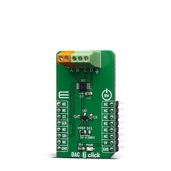
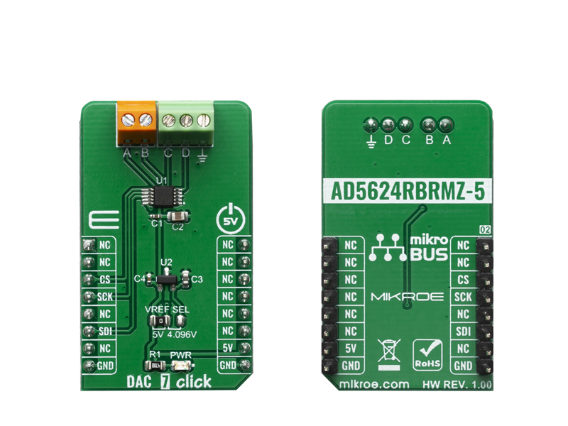
DAC 7 Click carries Texas Instruments AD5624R, a low-power four-channel, 12-bit buffered Digital-to-Analog Converter. AD5624R converts digital value to the corresponding voltage level using external voltage reference.

No Abuse Reported

Do you want to subscribe in order to receive notifications regarding "DAC 7 click" changes.

Do you want to unsubscribe in order to stop receiving notifications regarding "DAC 7 click" changes.

Do you want to report abuse regarding "DAC 7 click".

  • mikroSDK Library 2.0.0.0
  • Comments (0)
DOWNLOAD LINK RELATED COMPILER CONTAINS
mikroBasic PRO for ARM
  • lib
  • src
  • exa
  • hlp
  • hex
  • sch
  • pcb
  • doc
mikroBasic PRO for AVR
  • lib
  • src
  • exa
  • hlp
  • hex
  • sch
  • pcb
  • doc
mikroBasic PRO for dsPIC30/33 & PIC24
  • lib
  • src
  • exa
  • hlp
  • hex
  • sch
  • pcb
  • doc
mikroBasic PRO for FT90x
  • lib
  • src
  • exa
  • hlp
  • hex
  • sch
  • pcb
  • doc
mikroBasic PRO for PIC
  • lib
  • src
  • exa
  • hlp
  • hex
  • sch
  • pcb
  • doc
mikroBasic PRO for PIC32
  • lib
  • src
  • exa
  • hlp
  • hex
  • sch
  • pcb
  • doc
mikroC PRO for ARM
  • lib
  • src
  • exa
  • hlp
  • hex
  • sch
  • pcb
  • doc
mikroC PRO for AVR
  • lib
  • src
  • exa
  • hlp
  • hex
  • sch
  • pcb
  • doc
mikroC PRO for dsPIC30/33 & PIC24
  • lib
  • src
  • exa
  • hlp
  • hex
  • sch
  • pcb
  • doc
mikroC PRO for FT90x
  • lib
  • src
  • exa
  • hlp
  • hex
  • sch
  • pcb
  • doc
mikroC PRO for PIC
  • lib
  • src
  • exa
  • hlp
  • hex
  • sch
  • pcb
  • doc
mikroC PRO for PIC32
  • lib
  • src
  • exa
  • hlp
  • hex
  • sch
  • pcb
  • doc
mikroPascal PRO for ARM
  • lib
  • src
  • exa
  • hlp
  • hex
  • sch
  • pcb
  • doc
mikroPascal PRO for AVR
  • lib
  • src
  • exa
  • hlp
  • hex
  • sch
  • pcb
  • doc
mikroPascal PRO for dsPIC30/33 & PIC24
  • lib
  • src
  • exa
  • hlp
  • hex
  • sch
  • pcb
  • doc
mikroPascal PRO for FT90x
  • lib
  • src
  • exa
  • hlp
  • hex
  • sch
  • pcb
  • doc
mikroPascal PRO for PIC
  • lib
  • src
  • exa
  • hlp
  • hex
  • sch
  • pcb
  • doc
mikroPascal PRO for PIC32
  • lib
  • src
  • exa
  • hlp
  • hex
  • sch
  • pcb
  • doc

mikroSDK Library Blog

DAC 7 click

DAC 7 click

Native view of the DAC 7 click board.

View full image
DAC 7 click

DAC 7 click

Front and back view of the DAC 7 click board.

View full image

Library Description

The library covers all the necessary functions to control DAC 7 click board. Library performs a standard SPI interface communication.

Key functions:

  • DAC7_RETVAL_T dac7_set_ch_voltage ( uint8_t addr_ch, uint16_t vol_val, uint16_t v_ref_mv ) - Set the voltage values of the specified channel function.
  • DAC7_RETVAL_T dac7_set_power ( uint8_t pwr_en, uint8_t sel_ch ) - Set power mode function.
  • DAC7_RETVAL_T dac7_sw_reset ( void ) - Software reset function.

Examples description

The application is composed of three sections :

  • System Initialization - Initializes SPI, set CS pin as output and start to write log.
  • Application Initialization - Initialization driver enables - SPI, executes call software reset and all channels power on, also write log.
  • Application Task - (code snippet) This is an example that demonstrates the use of the DAC 7 Click board. In this example, we adjust the DAC output voltage from 1000 mV to 4000 mV for the channels, starting from channel A to channel D and set the DAC output voltage to 5000 mV for all channels. Results are being sent to the Usart Terminal where you can track their changes. All data logs write on USB uart changes every 5 sec.
void application_task ( )
{
    if ( dac7_set_ch_voltage ( DAC7_CHANNEL_A, 1000, v_ref_sel ) == DAC7_SUCCESS )
    {
        mikrobus_logWrite( "  Channel A : 1000 mV  ", _LOG_LINE );
    }
    else
    {
        mikrobus_logWrite( "        ERROR          ", _LOG_LINE );
        for ( ; ; );
    }

    Delay_ms( 5000 );
    mikrobus_logWrite( "-----------------------", _LOG_LINE );

    if ( dac7_set_ch_voltage ( DAC7_CHANNEL_B, 2000, v_ref_sel ) == DAC7_SUCCESS )
    {
        mikrobus_logWrite( "  Channel B : 2000 mV  ", _LOG_LINE );
    }
    else
    {
        mikrobus_logWrite( "        ERROR          ", _LOG_LINE );
        for ( ; ; );
    }

    Delay_ms( 5000 );
    mikrobus_logWrite( "-----------------------", _LOG_LINE );

    if ( dac7_set_ch_voltage ( DAC7_CHANNEL_C, 3000, v_ref_sel ) == DAC7_SUCCESS )
    {
        mikrobus_logWrite( "  Channel C : 3000 mV  ", _LOG_LINE );
    }
    else
    {
        mikrobus_logWrite( "        ERROR          ", _LOG_LINE );
        for ( ; ; );
    }

    Delay_ms( 5000 );
    mikrobus_logWrite( "-----------------------", _LOG_LINE );

    if ( dac7_set_ch_voltage ( DAC7_CHANNEL_D, 4000, v_ref_sel ) == DAC7_SUCCESS )
    {
        mikrobus_logWrite( "  Channel D : 4000 mV  ", _LOG_LINE );
    }
    else
    {
        mikrobus_logWrite( "        ERROR          ", _LOG_LINE );
        for ( ; ; );
    }

    Delay_ms( 5000 );
    mikrobus_logWrite( "-----------------------", _LOG_LINE );

    if ( dac7_set_ch_voltage ( DAC7_CHANNEL_ALL, 5000, v_ref_sel ) == DAC7_SUCCESS )
    {
        mikrobus_logWrite( " All Channels: 5000 mV ", _LOG_LINE );
    }
    else
    {
        mikrobus_logWrite( "        ERROR          ", _LOG_LINE );
        for ( ; ; );
    }

    Delay_ms( 5000 );
    mikrobus_logWrite( "-----------------------", _LOG_LINE );
}

Other mikroE Libraries used in the example:

  • SPI
  • UART

Additional notes and informations

Depending on the development board you are using, you may need USB UART clickUSB UART 2 click or RS232 click to connect to your PC, for development systems with no UART to USB interface available on the board. The terminal available in all MikroElektronika compilers, or any other terminal application of your choice, can be used to read the message.

ALSO FROM THIS AUTHOR

BUZZ 2 Click

0

BUZZ 2 Click carries the CMT-8540S-SMT magnetic buzzer transducer. The buzzer’s resonant frequency is 4kHz. The Click is designed to run on either 3.3V or 5V power supply.

[Learn More]

SPIRIT 2 Click

0

SPIRIT 2 Click features the SP1ML-915, an ultra-low power, fully integrated RF module, which operates at 915 MHz ISM band. This Click board™ can be used to add wireless connectivity to any application, requiring no extensive RF communication experience. The module integrates all the required components, including the 32-bit STM32L1 MCU, a compact chip antenna, and accompanying circuitry. The SP1ML-915 module supports several types of modulation schemes, including 2-FSK, GFSK, GMSK, OOK, and ASK, allowing it to fulfill different RF transmission requirements.

[Learn More]

Headphone AMP Click

0

Headphone Amp Click is a compact add-on board that contains a stereo headphone amplifier. This board features the LM4811, Boomer® audio power amplifier capable of delivering 105mW per channel with digital volume control from Texas Instruments. The Boomer® amplifiers are specifically designed to provide high-quality output power with a minimal amount of external components. Since the LM4811 does not require bootstrap capacitors or snubber networks, it is optimally suited for low-power portable systems. It features a digital volume control that sets the amplifier's gain from +12dB to −33dB in 16 discrete steps, in addition to a micro-power consumption Shutdown mode.

[Learn More]