TOP Contributors

  1. MIKROE (2663 codes)
  2. Alcides Ramos (358 codes)
  3. Shawon Shahryiar (307 codes)
  4. jm_palomino (112 codes)
  5. Chisanga Mumba (90 codes)
  6. S P (73 codes)
  7. dany (71 codes)
  8. MikroBUS.NET Team (35 codes)
  9. NART SCHINACKOW (34 codes)
  10. Armstrong Subero (27 codes)

Most Downloaded

  1. Timer Calculator (137099 times)
  2. FAT32 Library (70236 times)
  3. Network Ethernet Library (56124 times)
  4. USB Device Library (46434 times)
  5. Network WiFi Library (42077 times)
  6. FT800 Library (41387 times)
  7. GSM click (29116 times)
  8. mikroSDK (26562 times)
  9. PID Library (26489 times)
  10. microSD click (25487 times)
Libstock prefers package manager

Package Manager

We strongly encourage users to use Package manager for sharing their code on Libstock website, because it boosts your efficiency and leaves the end user with no room for error. [more info]

< Back
mikroSDK Library

Stepper 14 Click

Rating:

5

Author: MIKROE

Last Updated: 2020-07-01

Package Version: 1.0.0.0

mikroSDK Library: 1.0.0.0

Category: Stepper

Downloaded: 2579 times

Not followed.

License: MIT license  

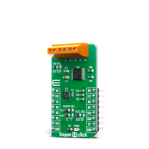
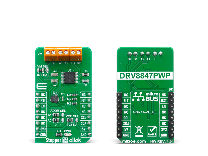
The Stepper 14 Click is a Click board that features the DRV8847PWPR, a step motor driver, from Texas Instruments. This Click boardâ„¢ provides a bipolar step motor controle, It features an H-bridge bipolar step motor driver, which supports full-, half-, quarter-, or eighth-step modes.

No Abuse Reported

Do you want to subscribe in order to receive notifications regarding "Stepper 14 Click" changes.

Do you want to unsubscribe in order to stop receiving notifications regarding "Stepper 14 Click" changes.

Do you want to report abuse regarding "Stepper 14 Click".

  • mikroSDK Library 2.0.0.0
  • Comments (0)
DOWNLOAD LINK RELATED COMPILER CONTAINS
mikroBasic PRO for ARM
  • lib
  • src
  • exa
  • hlp
  • hex
  • sch
  • pcb
  • doc
mikroBasic PRO for AVR
  • lib
  • src
  • exa
  • hlp
  • hex
  • sch
  • pcb
  • doc
mikroBasic PRO for dsPIC30/33 & PIC24
  • lib
  • src
  • exa
  • hlp
  • hex
  • sch
  • pcb
  • doc
mikroBasic PRO for FT90x
  • lib
  • src
  • exa
  • hlp
  • hex
  • sch
  • pcb
  • doc
mikroBasic PRO for PIC
  • lib
  • src
  • exa
  • hlp
  • hex
  • sch
  • pcb
  • doc
mikroBasic PRO for PIC32
  • lib
  • src
  • exa
  • hlp
  • hex
  • sch
  • pcb
  • doc
mikroC PRO for ARM
  • lib
  • src
  • exa
  • hlp
  • hex
  • sch
  • pcb
  • doc
mikroC PRO for AVR
  • lib
  • src
  • exa
  • hlp
  • hex
  • sch
  • pcb
  • doc
mikroC PRO for dsPIC30/33 & PIC24
  • lib
  • src
  • exa
  • hlp
  • hex
  • sch
  • pcb
  • doc
mikroC PRO for FT90x
  • lib
  • src
  • exa
  • hlp
  • hex
  • sch
  • pcb
  • doc
mikroC PRO for PIC
  • lib
  • src
  • exa
  • hlp
  • hex
  • sch
  • pcb
  • doc
mikroC PRO for PIC32
  • lib
  • src
  • exa
  • hlp
  • hex
  • sch
  • pcb
  • doc
mikroPascal PRO for ARM
  • lib
  • src
  • exa
  • hlp
  • hex
  • sch
  • pcb
  • doc
mikroPascal PRO for AVR
  • lib
  • src
  • exa
  • hlp
  • hex
  • sch
  • pcb
  • doc
mikroPascal PRO for dsPIC30/33 & PIC24
  • lib
  • src
  • exa
  • hlp
  • hex
  • sch
  • pcb
  • doc
mikroPascal PRO for FT90x
  • lib
  • src
  • exa
  • hlp
  • hex
  • sch
  • pcb
  • doc
mikroPascal PRO for PIC
  • lib
  • src
  • exa
  • hlp
  • hex
  • sch
  • pcb
  • doc
mikroPascal PRO for PIC32
  • lib
  • src
  • exa
  • hlp
  • hex
  • sch
  • pcb
  • doc

mikroSDK Library Blog

Stepper 14 Click

Stepper 14 Click

Native view of the Stepper 14 Click board.

View full image
Stepper 14 Click

Stepper 14 Click

Front and back view of the Stepper 14 Click board.

View full image

Library Description

The library covers all the necessary functions that enables the usage of the Stepper 14 Click board. It initializes and defines the I2C driver and drivers that allow full control of the device to the user. User can use the device to control forward and reverse motion, apply brake and coast functions for brushless dc motors, and forward and reverse motion in full step and half step for stepper motors.

Key functions:

  • void stepper14_step_motor ( uint8_t interface, uint8_t direction, uint32_t steps_no ); - Function is used to drive two or four wire stepper motor in user defined direction, one step at a time.
  • void stepper14_set_half_step ( uint8_t hl_step ); - Function is used to set specific half step.
  • void stepper14_control_mode_set ( uint8_t mode ); - Function is used to set mode of operation.

Examples description

The application is composed of three sections :

  • System Initialization - Initializes I2C module, LOG and GPIO structures, sets INT pin as input and RST and CS pins as output.
  • Application Initialization - Initalizes I2C driver, applies setup for 4-pin interface and writes an initial log.
  • Application Task - (code snippet) Demonstrates use of Stepper 14 click board by driving NEMA 17 stepper motor one turn forward and then one turn backward.
void application_task ( )
{
    mikrobus_logWrite( " Stepper motor makes one turn forward ", _LOG_LINE );
    stepper14_step_motor( STEPPER14_4_PIN_INTERFACE, STEPPER14_DIR_CW, 200 );
    Delay_ms( 1000 );
    
    mikrobus_logWrite( " Stepper motor makes one turn backward ", _LOG_LINE );
    stepper14_step_motor( STEPPER14_4_PIN_INTERFACE, STEPPER14_DIR_CCW, 200 );
    Delay_ms( 1000 );
}

Other mikroE Libraries used in the example:

  • I2C
  • UART

Additional notes and informations

Depending on the development board you are using, you may need USB UART clickUSB UART 2 click or RS232 click to connect to your PC, for development systems with no UART to USB interface available on the board. The terminal available in all MikroElektronika compilers, or any other terminal application of your choice, can be used to read the message.

ALSO FROM THIS AUTHOR

MCP2518FD click

5

MCP2518FD Click is a compact add-on board representing a complete CAN solution used as a control node in a CAN network. This board features the MCP2518FD, an external CAN FD controller with an SPI interface, and a high-speed CAN transceiver, the ATA6563, both from Microchip. The ATA6563, a low-level physical layer IC (PHY), provides a physical connection with the CAN bus itself, while the CAN controller MCP2518FD represents an interface between the MCU and the PHY. It features three operating modes with dedicated fail-safe features, remote wake-up via CAN, and ideally passive behavior when powered off on the CAN bus. This Click boardâ„¢ is suitable for developing a wide range of automotive diagnostic applications, even on MCUs that do not natively support CAN interface.

[Learn More]

LDC 1000 click

0

LDC1000 click carries the world's first inductance-to-digital converter IC, along with a detachable sensor (an LC tank comprising a 36-turn PCB coil and a 100pF 1% NPO capacitor). The LDC1000 IC has a sub-micron resolution in short range applications; the board is ideal for highly precise short range measurements of the position, motion or composition of conductive targets.

[Learn More]

Timer click

1

Timer click is a mikroBUS add-on board with Maxim’s DS1682 total elapsed time recorder. It holds an elapsed time counter (ETC) in conjunction with the ALARM pin. The alarm flag is one time programmable. The board communicates through I2C interface, with two additional pins: ALARM and EVENT. It uses either a 3.3V or a 5V power supply only.

[Learn More]