TOP Contributors

  1. MIKROE (2784 codes)
  2. Alcides Ramos (405 codes)
  3. Shawon Shahryiar (307 codes)
  4. jm_palomino (133 codes)
  5. Bugz Bensce (97 codes)
  6. S P (73 codes)
  7. dany (71 codes)
  8. MikroBUS.NET Team (35 codes)
  9. NART SCHINACKOW (34 codes)
  10. Armstrong Subero (27 codes)

Most Downloaded

  1. Timer Calculator (141292 times)
  2. FAT32 Library (74089 times)
  3. Network Ethernet Library (58715 times)
  4. USB Device Library (48826 times)
  5. Network WiFi Library (44525 times)
  6. FT800 Library (44074 times)
  7. GSM click (30805 times)
  8. mikroSDK (29659 times)
  9. PID Library (27355 times)
  10. microSD click (27251 times)
Libstock prefers package manager

Package Manager

We strongly encourage users to use Package manager for sharing their code on Libstock website, because it boosts your efficiency and leaves the end user with no room for error. [more info]

< Back
mikroSDK Library

ATA6571 click

Rating:

5

Author: MIKROE

Last Updated: 2020-12-28

Package Version: 1.0.0.0

mikroSDK Library: 1.0.0.0

Category: CAN

Downloaded: 3104 times

Not followed.

License: MIT license  

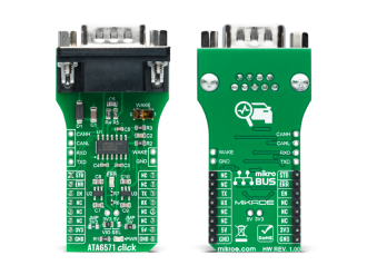
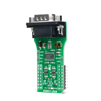
ATA6571 Click is a compact add-on board that contains a transceiver designed for high-speed CAN applications. This board features the ATA6571, a standalone high-speed CAN FD transceiver that interfaces a CAN protocol controller and the physical two-wire CAN bus from Microchip.

No Abuse Reported

Do you want to subscribe in order to receive notifications regarding "ATA6571 click" changes.

Do you want to unsubscribe in order to stop receiving notifications regarding "ATA6571 click" changes.

Do you want to report abuse regarding "ATA6571 click".
  • mikroSDK Library 2.0.0.0
  • Comments (0)
DOWNLOAD LINK RELATED COMPILER CONTAINS
mikroBasic PRO for ARM
  • lib
  • src
  • exa
  • hlp
  • hex
  • sch
  • pcb
  • doc
mikroBasic PRO for AVR
  • lib
  • src
  • exa
  • hlp
  • hex
  • sch
  • pcb
  • doc
mikroBasic PRO for dsPIC30/33 & PIC24
  • lib
  • src
  • exa
  • hlp
  • hex
  • sch
  • pcb
  • doc
mikroBasic PRO for FT90x
  • lib
  • src
  • exa
  • hlp
  • hex
  • sch
  • pcb
  • doc
mikroBasic PRO for PIC
  • lib
  • src
  • exa
  • hlp
  • hex
  • sch
  • pcb
  • doc
mikroBasic PRO for PIC32
  • lib
  • src
  • exa
  • hlp
  • hex
  • sch
  • pcb
  • doc
mikroC PRO for ARM
  • lib
  • src
  • exa
  • hlp
  • hex
  • sch
  • pcb
  • doc
mikroC PRO for AVR
  • lib
  • src
  • exa
  • hlp
  • hex
  • sch
  • pcb
  • doc
mikroC PRO for dsPIC30/33 & PIC24
  • lib
  • src
  • exa
  • hlp
  • hex
  • sch
  • pcb
  • doc
mikroC PRO for FT90x
  • lib
  • src
  • exa
  • hlp
  • hex
  • sch
  • pcb
  • doc
mikroC PRO for PIC
  • lib
  • src
  • exa
  • hlp
  • hex
  • sch
  • pcb
  • doc
mikroC PRO for PIC32
  • lib
  • src
  • exa
  • hlp
  • hex
  • sch
  • pcb
  • doc
mikroPascal PRO for ARM
  • lib
  • src
  • exa
  • hlp
  • hex
  • sch
  • pcb
  • doc
mikroPascal PRO for AVR
  • lib
  • src
  • exa
  • hlp
  • hex
  • sch
  • pcb
  • doc
mikroPascal PRO for dsPIC30/33 & PIC24
  • lib
  • src
  • exa
  • hlp
  • hex
  • sch
  • pcb
  • doc
mikroPascal PRO for FT90x
  • lib
  • src
  • exa
  • hlp
  • hex
  • sch
  • pcb
  • doc
mikroPascal PRO for PIC
  • lib
  • src
  • exa
  • hlp
  • hex
  • sch
  • pcb
  • doc
mikroPascal PRO for PIC32
  • lib
  • src
  • exa
  • hlp
  • hex
  • sch
  • pcb
  • doc

mikroSDK Library Blog

ATA6571 Click

ATA6571 Click

Native view of the ATA6571 Click board.

View full image
ATA6571 Click

ATA6571 Click

Front and back view of the ATA6571 Click board.

View full image

Library Description

The library covers all the necessary functions to control ATA6571 Click board™. Library performs a standard UART interface communication.

Key functions:

  • void ata6571_set_operation_mode ( uint8_t op_mode ) - Set device operation mode function.
  • void ata6571_write_byte ( uint8_t input ) - Write Single Byte.
  • uint8_t ata6571_read_byte( void ) - Read Single Byte.

Examples description

The application is composed of three sections :

  • System Initialization - Initializes UART used for communcation and another UART bus used for data logging.
  • Application Initialization - Initializes UART driver. In addition to this module is palced inside normal working mode cappable of tranmission and reception of data.
  • Application Task - (code snippet) - This is an example which demonstrates the use of ATA6571 Click board™. Tranismiter/Receiver task depend on uncommented code Receiver logging each received byte to the UART for data logging, while transmiter send message each 2 seconds.
void application_task ( )
{
    char tmp;
    uint8_t drdy_flag;

    if ( app_mode == APP_MODE_RECEIVER )
    {
        // RECEIVER - UART polling 

        drdy_flag = ata6571_byte_ready( );

        if ( 1 == drdy_flag )
        {
            tmp = ata6571_read_byte( );
            mikrobus_logWrite( &tmp, _LOG_BYTE );
        }
    }
    else
    {
        // TRANSMITER - TX each 2 sec
      
        for ( tmp = 0; tmp < 9; tmp++ )
        {
            ata6571_write_byte( demo_message_data[ tmp ] );
            Delay_ms( 100 );
        }
        
        mikrobus_logWrite( "   MESSAGE SENT!    ", _LOG_LINE );
        mikrobus_logWrite( "-------------------", _LOG_LINE );
        Delay_ms( 2000 );
    }
}

Other mikroE Libraries used in the example:

  • UART

Additional notes and informations

Depending on the development board you are using, you may need USB UART clickUSB UART 2 click or RS232 click to connect to your PC, for development systems with no UART to USB interface available on the board. The terminal available in all MikroElektronika compilers, or any other terminal application of your choice, can be used to read the message.

ALSO FROM THIS AUTHOR

Oximeter 5 Click

0

Oximeter 5 Click is a compact add-on board suitable for measuring blood oxygen saturation. This board features the MAX30102, integrated pulse oximetry, and heart-rate monitor module from Analog Devices. The MAX30102 includes internal LEDs, photodetectors, optical elements, and low-noise electronics with ambient light rejection. It operates on a single 1.8V power supply acquired from both mikroBUS™ power rails for the internal LEDs, communicating through a standard I2C compatible interface. The MAX30102 can be shut down through software with zero standby current, allowing the power rails to remain powered at all times.

[Learn More]

Stepper 3 Click

0

Stepper 3 Click is designed to drive unipolar stepper motors, with a supply voltage applied to the common wire. The current flows through the common wire and the motor coil, via the activated current sink driver, to the ground. This Click board™ uses the ULN2003A, a high voltage and current Darlington transistors array IC, as the sink driver. This IC is an ideal solution for this purpose, as it has seven high power Darlington output stages, activated by TTL/CMOS logic level signals, applied to the control pins. This allows driving unipolar stepper motors with up to 30V and 500mA per coil.

[Learn More]

I2C Demo

0

The application demonstrates I2C SDK functionality.

[Learn More]