
We strongly encourage users to use Package manager for sharing their code on Libstock website, because it boosts your efficiency and leaves the end user with no room for error. [more info]

Rating:
Author: Vladimir Savić
Last Updated: 2016-02-19
Package Version: 1.0.0.2
Example: 1.0.0.0
Category: Motor Control
Downloaded: 2417 times
Followed by: 1 user
License: MIT license
This example is related to stepper motor controller modeled by state machine.
It is based on my previous example - Injection System Behavior.
New version 1.0.0.2 - TM encoding modes, configurable TM priorities ...
Do you want to subscribe in order to receive notifications regarding "Stepper Motor Controller" changes.
Do you want to unsubscribe in order to stop receiving notifications regarding "Stepper Motor Controller" changes.
Do you want to report abuse regarding "Stepper Motor Controller".
| DOWNLOAD LINK | RELATED COMPILER | CONTAINS |
|---|---|---|
| 1377040905_stepper_motor_co_mikroc_8051.zip [15.63KB] | mikroC PRO for 8051 |
|
This stepper motor controller is base on my previous example related to "Injection System Behavior". As You can see from related YouTube video, stepper motor behavior could be easily changed by injection into the generic state machine. Injection is done over RS232 and USART terminal.
Provided material for download contains several bin files related to stepper motor behavior.
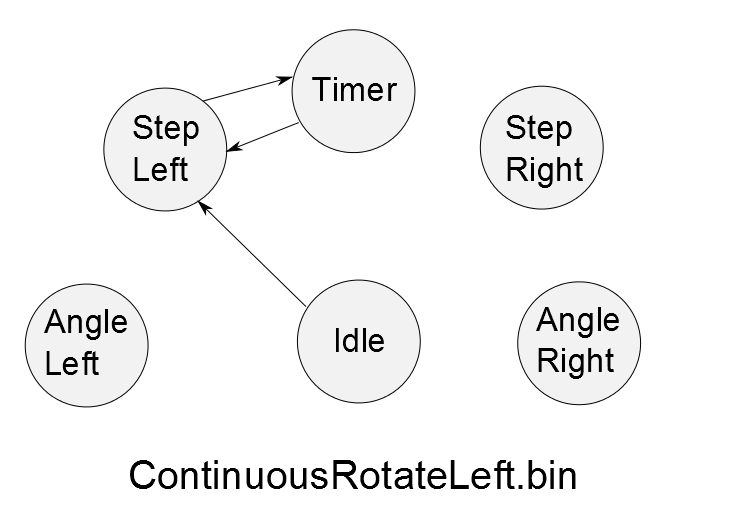
ContinuousRotateLeft.bin - transition matrix - stepper behavior #1
ContinuousRotateLeftAngle.bin - transition matrix - stepper behavior #2
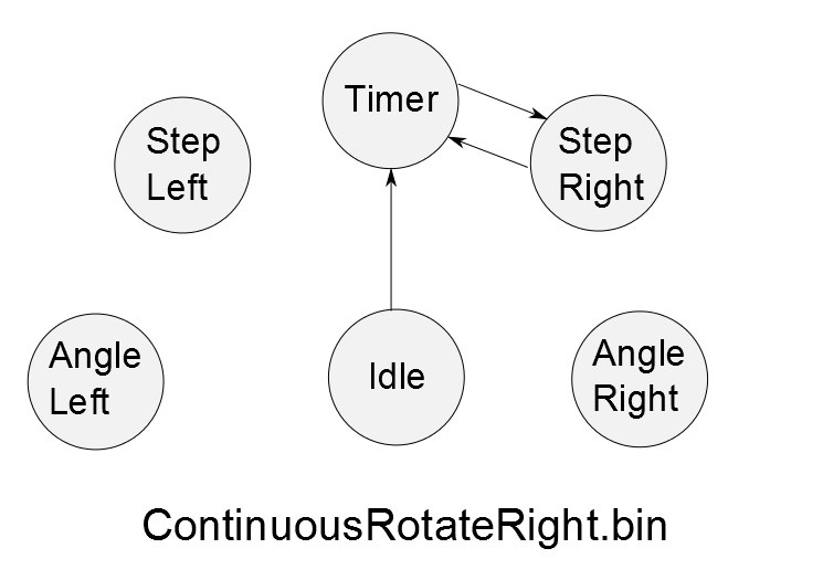
ContinuousRotateRight.bin - transition matrix - stepper behavior #3
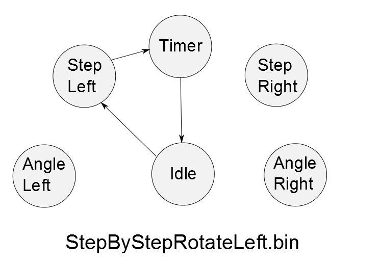
StepByStepRotateLeft.bin - transition matrix - stepper behavior #4
StepByStepRotateRight.bin - transition matrix - stepper behavior #5
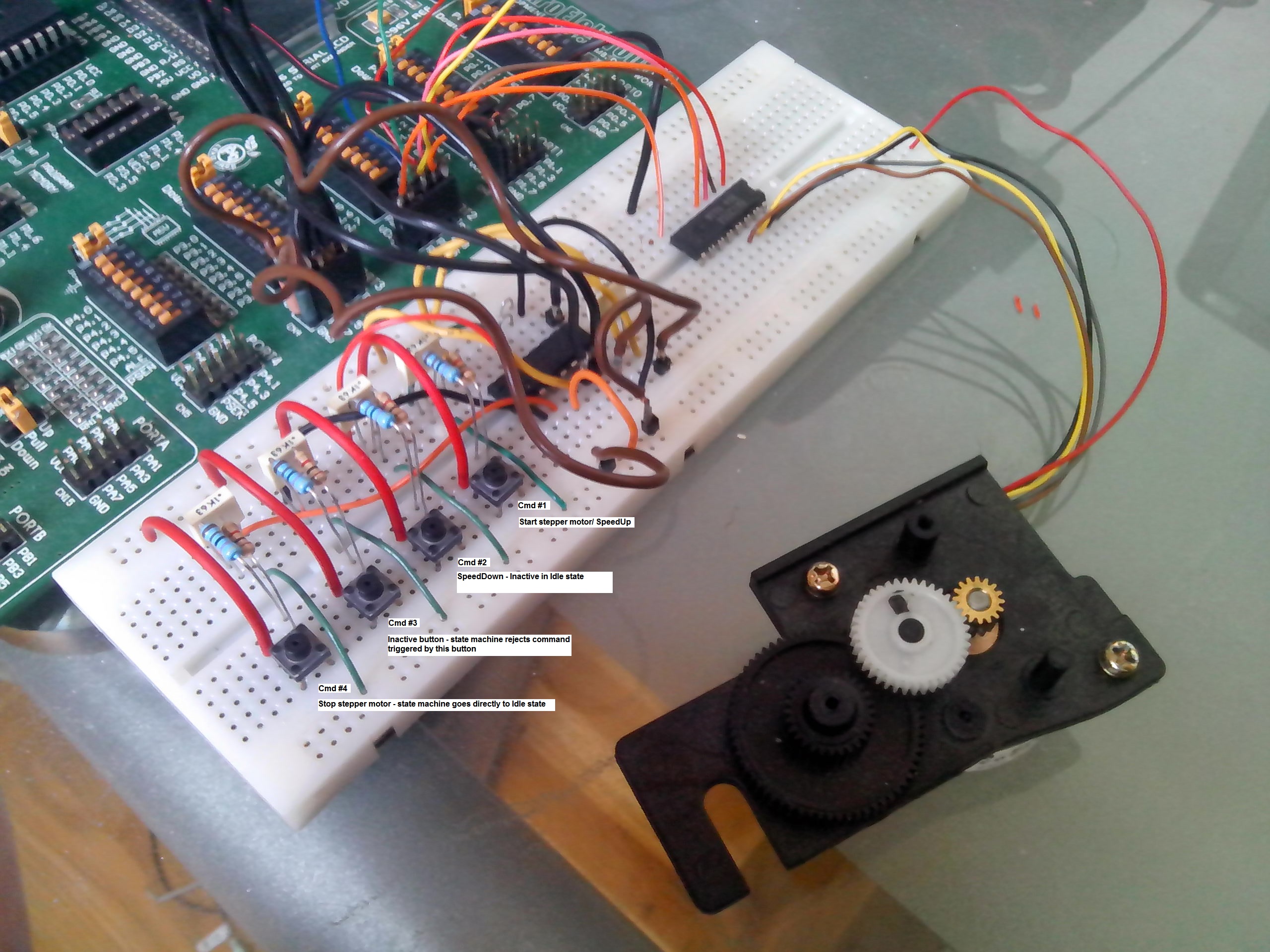
For more details please look at "Injection System Behavior" example Electronics: beside priority encoder for external commands encoding, interface between 8051 MCU and stepper motor is done over device driver BA12004 IC (replacement: ULN2XXX series - http://www.zilsel-invent.com/uln2xxx.xhtml motor driver kit) As You can see from state diagrams, stepper motor is modeled as state machine. It is important to define all stepper motor states in order to achieve desired behaviors. ------------------------------------------------------------------------------------------------------------------------------------------------ Version: 1.0.0.1
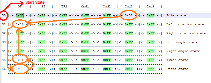
Stepper Motor - Speed Controller Changes: Additional state "SpeedState" is added in order to achieve motor speed regulation. Interrupt handler routines are removed from state machine - timers and external interrupts will be handled by "default state method" as all other external commands encoded by priority encoder. Direct and indirect transition flags are optimized - instead of two BYTE fields only one BYTE field is used to indicate state flags. Currently only two MSB are used in order to provide state flags. Transition matrix is 50 bytes long - first byte for start state and 49 for system behavior. Currently transition matrix takes a lot of unused memory (0xFF fields, last attached screen shot) and it will be modified soon by adding transition matrix mode. Each transition matrix mode will present number of bits for state encoding.
Notes: Provided material for download includes ContinuousRotation-SpeedController.bin file as speed controller example. By appending seven additional bytes at the end of the file, bin files from previous version could be easily expanded to 50 bytes. ------------------------------------------------------------------------------------------------------------------------------------------------ Version: 1.0.0.2
Main changes are made on transition matrix, by adding state encoding mode. Currently there are two encoding modes called xModes: x1Mode: default mode, one BYTE per state allows 255 different kind of states (too large transition matrix structure for small memory models) x2Mode: it is used by version 1.0.0.2, one BYTE per two state allows 15 different kind of states (requires less amount of space than x1Mode). Suitable for state machines with <= 15 states. DT, PS and CMD transitions are no longer fixed. State flag is used to set transition priorities. State machine engine is also changed regarding transition matrix changes. For more details look at : TransitionMatrix.h, TransitionMatrix.c, StateMachine.h and StateMachine.c
Related YouTube videos and more transition matrix examples (bin files) will be available as soon as possible.
For any question, please contact me.

version 1.0.0.2, stepper motor start rotation in one direction. When desired angle is reached, stepper motor change rotation in opposite direction. Cmd#1 command is also used to speed up stepper motor. Cmd#2 is used to slow down motor speed. Cmd#4 is used
Watch on YouTubeVersion: 1.0.0.1; Stepper Motor - Speed Controller
Watch on YouTube
Version: 1.0.0.0; Version: 1.0.0.1; Only 3 states are required to achieve continuous left rotation.
View full image
Version: 1.0.0.0; Version: 1.0.0.1; Only 3 states are required to achieve step by step rotation. Idle state is initial state for each step.
View full image
Version: 1.0.0.0; Version: 1.0.0.1; Only 3 states are required to achieve continuous right rotation.
View full image
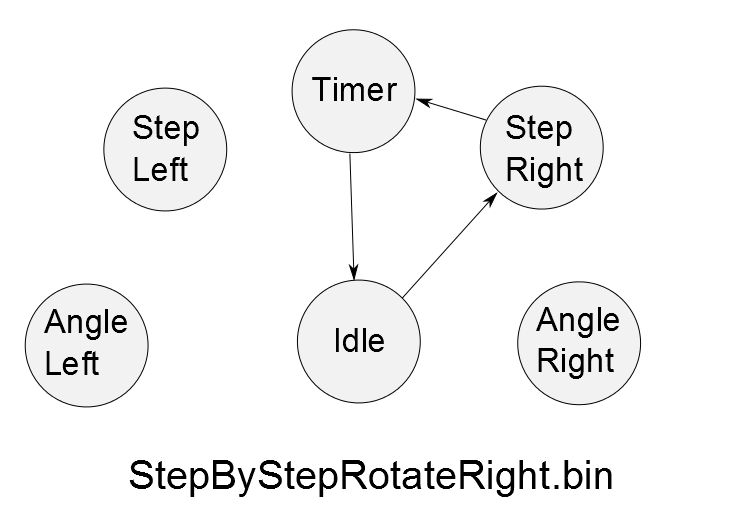
Version: 1.0.0.0; Version: 1.0.0.1; Only 3 states are required to achieve step by step right rotation.
View full image
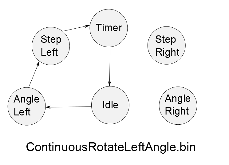
Version: 1.0.0.0; Version: 1.0.0.1; Four state are required in order to achieve this stepper motor behavior. Stepper motor turns one step at a time until reach maximum allowed left step angle. For example: if Left Angle is set to 90, maximum allowed st
View full image
Version: 1.0.0.1; Speed Controller - Transition Matrix - 49 BYTE long. Only four states required for speed regulation. A lot of unused TM fields - it will be optimized by TM mode where each mode describe state encoding mode...
View full image


