TOP Contributors

  1. MIKROE (2784 codes)
  2. Alcides Ramos (405 codes)
  3. Shawon Shahryiar (307 codes)
  4. jm_palomino (133 codes)
  5. Bugz Bensce (97 codes)
  6. S P (73 codes)
  7. dany (71 codes)
  8. MikroBUS.NET Team (35 codes)
  9. NART SCHINACKOW (34 codes)
  10. Armstrong Subero (27 codes)

Most Downloaded

  1. Timer Calculator (141361 times)
  2. FAT32 Library (74205 times)
  3. Network Ethernet Library (58776 times)
  4. USB Device Library (48854 times)
  5. Network WiFi Library (44564 times)
  6. FT800 Library (44149 times)
  7. GSM click (30883 times)
  8. mikroSDK (29739 times)
  9. PID Library (27372 times)
  10. microSD click (27309 times)
Libstock prefers package manager

Package Manager

We strongly encourage users to use Package manager for sharing their code on Libstock website, because it boosts your efficiency and leaves the end user with no room for error. [more info]

< Back
Project

Designing a Microprocessor from Scratch

Rating:

0

Author: Val Gretchev

Last Updated: 2014-05-29

Package Version: 1.0.0.0

Category: Other Codes

Downloaded: 555 times

Not followed.

License: MIT license  

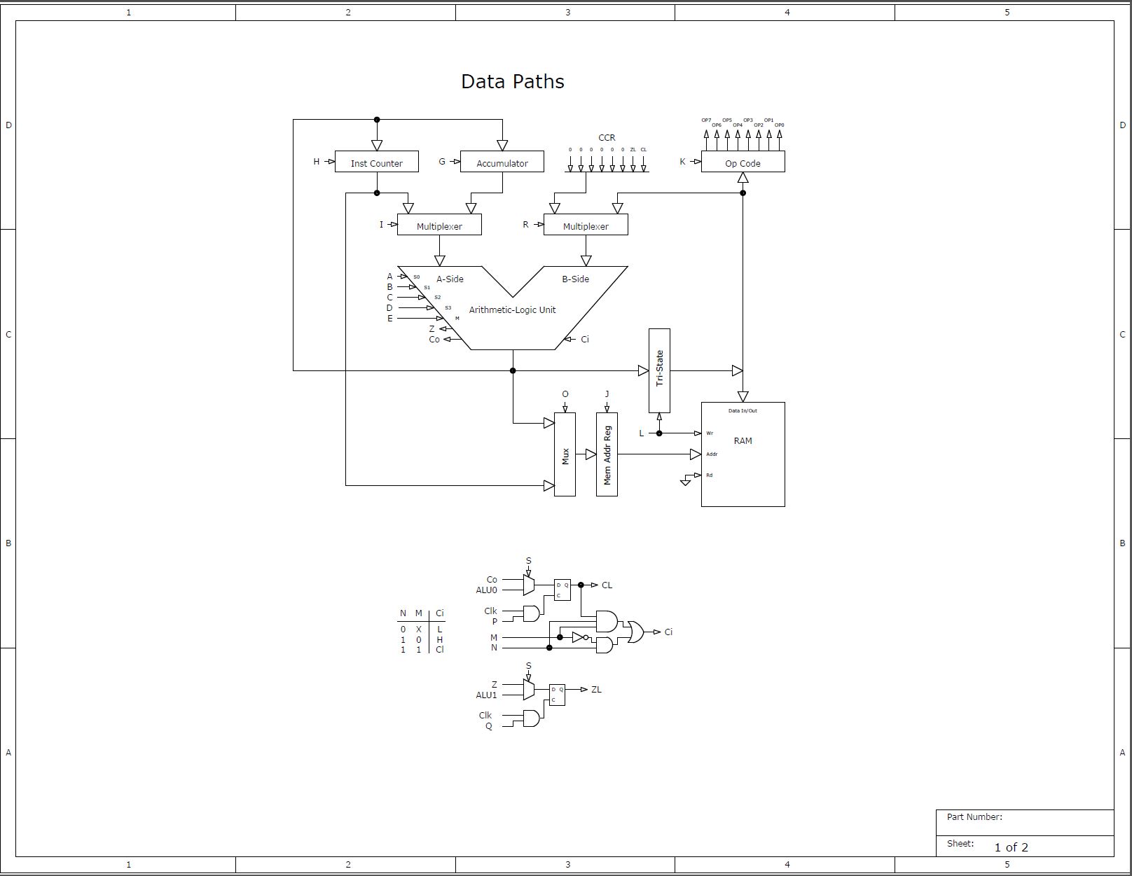
Many students in electronics learn how to use and program a microprocessor but very few know what goes on inside the chip itself. This project will give the reader insight into the inner workings of a very simple 8-bit microprocessor that can be extended to more powerful designs.

No Abuse Reported

Do you want to subscribe in order to receive notifications regarding "Designing a Microprocessor from Scratch " changes.

Do you want to unsubscribe in order to stop receiving notifications regarding "Designing a Microprocessor from Scratch " changes.

Do you want to report abuse regarding "Designing a Microprocessor from Scratch ".

  • Information
  • Comments (0)
DOWNLOAD LINK RELATED COMPILER CONTAINS
Other Compiler
  • lib
  • src
  • exa
  • hlp
  • hex
  • sch
  • pcb
  • doc

Project Blog

Data Paths

Data Paths

This diagram depicts how the data moves from one resource to another.

View full image
PicoCode Sequencer

PicoCode Sequencer

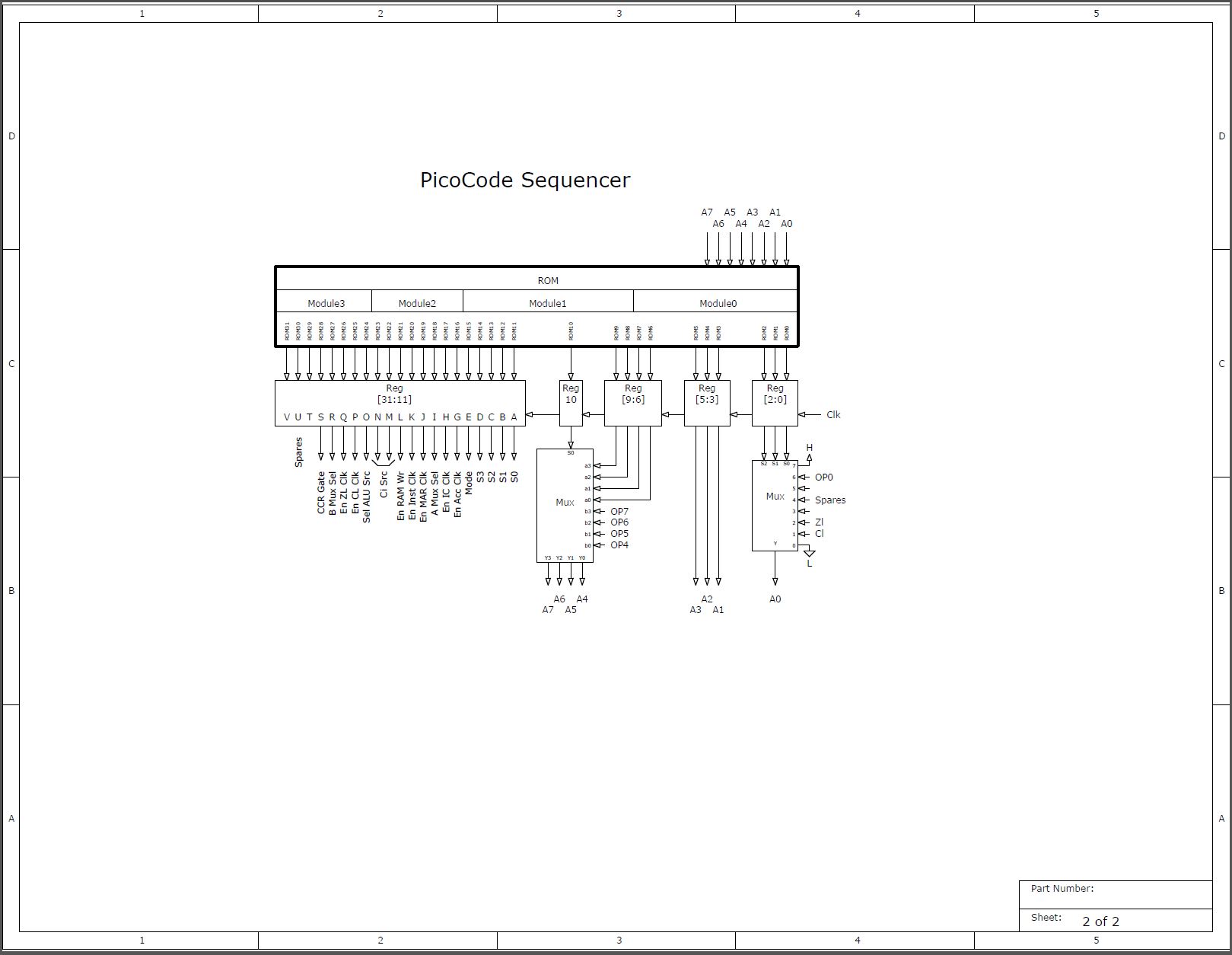
This logic is where the instructions in RAM are interpreted and the data paths manipulated to execute those instructions.

View full image


  1. Introduction

    A long time ago, before integrated microprocessors, there was a wonderful chip with a number designation of 74181 (a 4-bit ALU). This was a time when you made up a microprocessor using many TTL logic chips. Two or four of these ALU chips made the core of a microprocessor. For a 16-bit ALU, there was a companion chip designated 74182 which was used to speed up the carry output.


    These chips are no longer readily available but the published circuit diagram makes it useful for simulation (see datasheets included in this package).


    Purpose

    Many students in Electrical Engineering learn how to use and program a microprocessor but very few know what goes on inside. This article will give the reader insight into the inner workings of a very simple microprocessor that can be extended to more powerful designs. I will use a visual method of ANDs ORs and Inverters to implement the data paths and controls. In order to do that, we have to use a logic simulator to test the design. Fortunately, there is a simple free program (CEDAR Logic) that accomplishes this task and is easy to learn.

    You can download it from the following URL:

    http://sourceforge.net/projects/cedarlogic/?source=dlp


    Design Description

    The file BlockDiagram.pdf shows the data paths that feed the ALU and RAM. There is only 1 Accumulator for simplicity. Control logic is centered on a 32-bit ROM that implements the sequences for fetching data from RAM and decoding the instructions. You can view the sequences as a state diagram but traditionally it’s called horizontal programming (see PicoCode.pdf). Each program word is 32 bits wide and includes the next address of the flow. Two way branching is possible on the Carry Latch, Zero Latch and bit 0 of the Op Code Register. A 16 way branch can be performed on the high-order 4 bits of the Op Code Register.

    As mentioned before, the Arithmetic-Logic-Unit is based on the 74181 datasheet. Refer to ALU.jpg for an image of the circuit as presented by the simulator. The page illustrated by A-SidePath.jpg shows the data paths feeding the A-side of the ALU. SystemRAM.jpg shows the B-side data path for the ALU. Sequence.jpg and ClockAndDisplay.jpg complete the entire design. 


ALSO FROM THIS AUTHOR

Vehicle Detection by Means of Inductive Loop

1

This project implements a loop oscillator circuit and a buried loop coil to detect large metal objects (such as a car). External components are kept to a minimum and oscillator frequency detection is done in software. This project uses a mikromedia plus for STM32 board with shield but any other fast MPU board should work.

[Learn More]

Using a Shaft Encoder with MINI-M4 for STM32

0

This example shows how to connect a shaft encoder to a MPU board and provides a state machine decoder that can be used for many useful applications where a rotating dial inputs positional information. This data can be used for display purposes or for converting into analog signal by passing it to the internal DACs.

[Learn More]

Traffic Flow Recorder (TFR)

0

This project combines several examples into a single application implementing a traffic movement data logger. The collected data can be used to justify signal lights or to change the signaling sequence of existing lights. The hardware used for this project is mikromedia for Stellaris® M3 board.

[Learn More]