TOP Contributors

  1. MIKROE (2784 codes)
  2. Alcides Ramos (405 codes)
  3. Shawon Shahryiar (307 codes)
  4. jm_palomino (133 codes)
  5. Bugz Bensce (97 codes)
  6. S P (73 codes)
  7. dany (71 codes)
  8. MikroBUS.NET Team (35 codes)
  9. NART SCHINACKOW (34 codes)
  10. Armstrong Subero (27 codes)

Most Downloaded

  1. Timer Calculator (142024 times)
  2. FAT32 Library (75253 times)
  3. Network Ethernet Library (59472 times)
  4. USB Device Library (49492 times)
  5. Network WiFi Library (45268 times)
  6. FT800 Library (44880 times)
  7. GSM click (31415 times)
  8. mikroSDK (30402 times)
  9. microSD click (27778 times)
  10. PID Library (27614 times)
Libstock prefers package manager

Package Manager

We strongly encourage users to use Package manager for sharing their code on Libstock website, because it boosts your efficiency and leaves the end user with no room for error. [more info]

< Back
mikroSDK Library

GSM click

Rating:

0

Author: MIKROE

Last Updated: 2018-01-21

Package Version: 1.0.0.1

mikroSDK Library: 1.0.0.0

Category: GSM/LTE

Downloaded: 31415 times

Followed by: 4 users

License: MIT license  

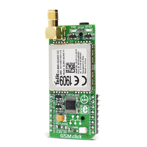
GSM click is the easiest way to add GSM/GPRS communication to your device. The click features Telit's GL865-QUAD. GSM click runs either on 3.3V or 5V power supply and communicates with the target microcontroller via UART interface.

No Abuse Reported

Do you want to subscribe in order to receive notifications regarding "GSM click" changes.

Do you want to unsubscribe in order to stop receiving notifications regarding "GSM click" changes.

Do you want to report abuse regarding "GSM click".

  • mikroSDK Library 2.0.0.0
  • Comments (5)
DOWNLOAD LINK RELATED COMPILER CONTAINS
mikroBasic PRO for ARM
  • lib
  • src
  • exa
  • hlp
  • hex
  • sch
  • pcb
  • doc
mikroBasic PRO for AVR
  • lib
  • src
  • exa
  • hlp
  • hex
  • sch
  • pcb
  • doc
mikroBasic PRO for dsPIC30/33 & PIC24
  • lib
  • src
  • exa
  • hlp
  • hex
  • sch
  • pcb
  • doc
mikroBasic PRO for FT90x
  • lib
  • src
  • exa
  • hlp
  • hex
  • sch
  • pcb
  • doc
mikroBasic PRO for PIC
  • lib
  • src
  • exa
  • hlp
  • hex
  • sch
  • pcb
  • doc
mikroBasic PRO for PIC32
  • lib
  • src
  • exa
  • hlp
  • hex
  • sch
  • pcb
  • doc
mikroC PRO for ARM
  • lib
  • src
  • exa
  • hlp
  • hex
  • sch
  • pcb
  • doc
mikroC PRO for AVR
  • lib
  • src
  • exa
  • hlp
  • hex
  • sch
  • pcb
  • doc
mikroC PRO for dsPIC30/33 & PIC24
  • lib
  • src
  • exa
  • hlp
  • hex
  • sch
  • pcb
  • doc
mikroC PRO for FT90x
  • lib
  • src
  • exa
  • hlp
  • hex
  • sch
  • pcb
  • doc
mikroC PRO for PIC
  • lib
  • src
  • exa
  • hlp
  • hex
  • sch
  • pcb
  • doc
mikroC PRO for PIC32
  • lib
  • src
  • exa
  • hlp
  • hex
  • sch
  • pcb
  • doc
mikroPascal PRO for ARM
  • lib
  • src
  • exa
  • hlp
  • hex
  • sch
  • pcb
  • doc
mikroPascal PRO for AVR
  • lib
  • src
  • exa
  • hlp
  • hex
  • sch
  • pcb
  • doc
mikroPascal PRO for dsPIC30/33 & PIC24
  • lib
  • src
  • exa
  • hlp
  • hex
  • sch
  • pcb
  • doc
mikroPascal PRO for FT90x
  • lib
  • src
  • exa
  • hlp
  • hex
  • sch
  • pcb
  • doc
mikroPascal PRO for PIC
  • lib
  • src
  • exa
  • hlp
  • hex
  • sch
  • pcb
  • doc
mikroPascal PRO for PIC32
  • lib
  • src
  • exa
  • hlp
  • hex
  • sch
  • pcb
  • doc

mikroSDK Library Blog

GSM click

GSM click

Native view of the GSM click board.

View full image
GSM click

GSM click

Front and back view of the GSM click board.

View full image

Library Description

The library carries a generic command parser adopted for AT command based modules. Generic parser.

Key functions:

gsm_cmdSingle - Sends a provided command to the module.

gsm_setHandler - Handler assignation to the provided command.

gsm_modulePower - Turns on the module.

Examples Description

The example demo application waits for the cal, and after the call is received the parser will get hang up.

This code snippet shows how a generic parser should be properly initialized. Before the initialization, the module must be turned on, and in addition to this, the hardware flow control should also be turned on.
Commands:

  • The first command negotiates the baud rate with the module.
  • The second command turns the echo off.
  • The third command enables hardware flow control - necessary in case of UART polling.
  • The fourth command sets up default message format.
     
void applicationInit()
{
// MODULE POWER ON
 gsm_hfcEnable( true );
 gsm_modulePower( true );

// MODULE INIT
 gsm_cmdSingle( "AT" );
 gsm_cmdSingle( "ATE0" );
 gsm_cmdSingle( "AT+IFC=2,2" );
 gsm_cmdSingle( "AT+CMGF=1" );
}

Along with the demo application, timer initialization functions are provided. Note that the timer is configured according to the default development system and MCUs, changing the system or MCU may require an update of timer init and timer ISR functions.

Additional notes and information

Depending on the development board you are using, you may need USB UART click,  USB UART 2 click or RS232 click to connect to your PC, for development systems with no UART to USB interface available on the board. The terminal available in all MikroElektronika compilers, or any other terminal application of your choice, can be used to read the message.

ALSO FROM THIS AUTHOR

RMS to DC Click

0

RMS to DC Click is a Click board™ that is used to convert the RMS of the input signal into a DC voltage, with a value directly readable over the I2C interface.

[Learn More]

NINA-W152 Click

0

NINA-W152 Click is a compact add-on board designed for seamless integration of Wi-Fi and Bluetooth communication into your projects. Based on the NINA-W152 multi-radio module from u-blox, this Click board™ provides dual-mode wireless connectivity, including Wi-Fi 802.11b/g/n and Bluetooth BR/EDR v4.2+EDR and Bluetooth Low Energy v4.2. It features an internal PIFA antenna for optimal performance and supports communication through UART and SPI interfaces, with secure boot and enterprise-level security protocols (WPA2/WPA3) ensuring reliable operation.

[Learn More]

Matrix R Click

0

Matrix R Click is a mikroBUS add-on board with two red 5x7 matrices driven by two MAX7219 8-bit LED Display Drivers. The active area of each matrix is 7.62mm high and 5.08 mm wide. 7x5 is a standard resolution for displaying ASCII characters, so the Click is essentially a dual-character display capable of showing letters in more readable typefaces compared to a 14-segment display. The Click communicates with the target MCU through the mikroBUS:tm: SPI interface with two separate Chip Select lines for each matrix (CSL for the left, CSR for the right). This board is designed to use a 5V power supply.

[Learn More]