
We strongly encourage users to use Package manager for sharing their code on Libstock website, because it boosts your efficiency and leaves the end user with no room for error. [more info]

Rating:
Author: Dick Berry
Last Updated: 2016-02-18
Package Version: 3.0.0.0
Example: 1.0.0.0
Category: Light control
Downloaded: 605 times
Followed by: 2 users
License: MIT license
Test software to demonstrate the capabilities of the STP16CPC05 serial in 16 bit shift register with Current Limiting to light 12 LED's Rev 2.0
Rev 3.0 is the end of this project. I added a couple more test and am including a link to a Video on You Tube.
Do you want to subscribe in order to receive notifications regarding "Example of Using a STP16CPC05 16 Bit Serial in Shift register to light LED's" changes.
Do you want to unsubscribe in order to stop receiving notifications regarding "Example of Using a STP16CPC05 16 Bit Serial in Shift register to light LED's" changes.
Do you want to report abuse regarding "Example of Using a STP16CPC05 16 Bit Serial in Shift register to light LED's".
| DOWNLOAD LINK | RELATED COMPILER | CONTAINS |
|---|---|---|
| 1409881047_example_of_using_mikrobasic_pic.zip [100.37KB] | mikroBasic PRO for PIC |
|
I found these KOMANI Gaming Machine LED boards surplus for $20 for a set of five. I thought it would be a fun project to sort them out ans see if I could get some software to blink them. I reversed Engineered the board and found they use Three STP16CPC05 Serial in Shift registers with programmable current limiting. I've included the schematic in the zip file. If you need to expand outputs these chips work very well and have the capability to drive LED's directly in a 20 Pin SSOP Package' The interface is simple just Clock, Data, and a Latch Enable Bit. The outputs are not affected while shifting data in and are transferred with a Latch Enable pulse. I tested the board at 8 Mhz, 32 Mhz, and 64 Mhz with a 18F45K22 and it works at all speeds. I'll attach some pictures of timing at 64 Mhz. A fun little project. More pictures in the zip.
Thanks for Looking Dick
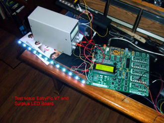
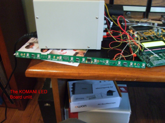
Labeled KOMANI Horz-LED. 12 bright LED's with three STP16CPC05 chips daisy chained together. Five boards were $20 at Electronic Goldmine.
View full image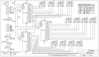
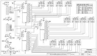
I reversed engineered the Board and entered the schematic into Express SCH. The Express SCH file is in the zip.
View full image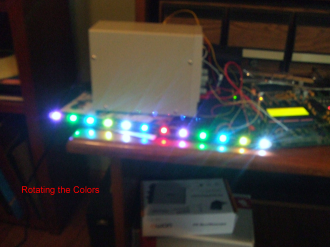
By sending just four bits the colors can be rotated right to lrft through the shift registers.
View full image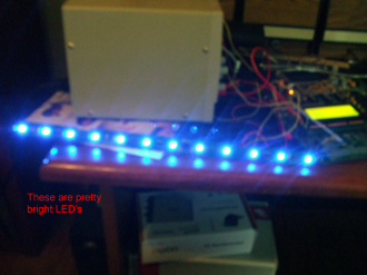
I rotate through all the Colors including OFF by pressing the E.0 button. While on any color the software flashes at a 1.5 Second Period.
View full imageRev-02 2014/08/27 added a couple tests and cleaned up the source to eliminate
all the lables Main_xx to something that relates to the test in progress
Made turning OFF all the LED's a Sub Procedure and included some const's
for describing the numbers I had in the source. Also made a dummy test
at the end for the next test I haven't thought up yet.
I also have three of the boards daisy chained now.
This version is a much smaller ZIP file because I removed the DOC's folder and put it on the ONE Drive here
https://onedrive.live.com/?cid=AE67FFF392766057&id=AE67FFF392766057%215774
But it hasn't changed from the original. Now you can download only the files in the DOC's folder you want.
Thanks For Looking
Dick
I had the binary color codes wrong in the table so here is a correction.
View full imageI added a couple more tests in Rev 3.0 and made a Video. You can view the Video here.
https://www.youtube.com/watch?v=Uq11tz4TwSY
Thanks for Looking
Dick