TOP Contributors

  1. MIKROE (2784 codes)
  2. Alcides Ramos (405 codes)
  3. Shawon Shahryiar (307 codes)
  4. jm_palomino (133 codes)
  5. Bugz Bensce (97 codes)
  6. S P (73 codes)
  7. dany (71 codes)
  8. MikroBUS.NET Team (35 codes)
  9. NART SCHINACKOW (34 codes)
  10. Armstrong Subero (27 codes)

Most Downloaded

  1. Timer Calculator (141590 times)
  2. FAT32 Library (74540 times)
  3. Network Ethernet Library (59060 times)
  4. USB Device Library (49088 times)
  5. Network WiFi Library (44835 times)
  6. FT800 Library (44398 times)
  7. GSM click (31067 times)
  8. mikroSDK (29935 times)
  9. microSD click (27504 times)
  10. PID Library (27492 times)
Libstock prefers package manager

Package Manager

We strongly encourage users to use Package manager for sharing their code on Libstock website, because it boosts your efficiency and leaves the end user with no room for error. [more info]

< Back
mikroSDK Library

ccRF 2 click

Rating:

1

Author: MIKROE

Last Updated: 2019-07-31

Package Version: 1.0.0.1

mikroSDK Library: 1.0.0.0

Category: Sub-1 GHz Transceivers

Downloaded: 5260 times

Not followed.

License: MIT license  

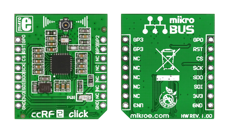
This is a sample program which demonstrates the use of ccRF2 click. Programmer uses RF module for communication between two development systems. Each module can be used as transmitter and receiver.

No Abuse Reported

Do you want to subscribe in order to receive notifications regarding "ccRF 2 click" changes.

Do you want to unsubscribe in order to stop receiving notifications regarding "ccRF 2 click" changes.

Do you want to report abuse regarding "ccRF 2 click".

  • mikroSDK Library 2.0.0.0
  • Comments (1)
DOWNLOAD LINK RELATED COMPILER CONTAINS
mikroBasic PRO for ARM
  • lib
  • src
  • exa
  • hlp
  • hex
  • sch
  • pcb
  • doc
mikroBasic PRO for AVR
  • lib
  • src
  • exa
  • hlp
  • hex
  • sch
  • pcb
  • doc
mikroBasic PRO for dsPIC30/33 & PIC24
  • lib
  • src
  • exa
  • hlp
  • hex
  • sch
  • pcb
  • doc
mikroBasic PRO for FT90x
  • lib
  • src
  • exa
  • hlp
  • hex
  • sch
  • pcb
  • doc
mikroBasic PRO for PIC
  • lib
  • src
  • exa
  • hlp
  • hex
  • sch
  • pcb
  • doc
mikroBasic PRO for PIC32
  • lib
  • src
  • exa
  • hlp
  • hex
  • sch
  • pcb
  • doc
mikroC PRO for ARM
  • lib
  • src
  • exa
  • hlp
  • hex
  • sch
  • pcb
  • doc
mikroC PRO for AVR
  • lib
  • src
  • exa
  • hlp
  • hex
  • sch
  • pcb
  • doc
mikroC PRO for dsPIC30/33 & PIC24
  • lib
  • src
  • exa
  • hlp
  • hex
  • sch
  • pcb
  • doc
mikroC PRO for FT90x
  • lib
  • src
  • exa
  • hlp
  • hex
  • sch
  • pcb
  • doc
mikroC PRO for PIC
  • lib
  • src
  • exa
  • hlp
  • hex
  • sch
  • pcb
  • doc
mikroC PRO for PIC32
  • lib
  • src
  • exa
  • hlp
  • hex
  • sch
  • pcb
  • doc
mikroPascal PRO for ARM
  • lib
  • src
  • exa
  • hlp
  • hex
  • sch
  • pcb
  • doc
mikroPascal PRO for AVR
  • lib
  • src
  • exa
  • hlp
  • hex
  • sch
  • pcb
  • doc
mikroPascal PRO for dsPIC30/33 & PIC24
  • lib
  • src
  • exa
  • hlp
  • hex
  • sch
  • pcb
  • doc
mikroPascal PRO for FT90x
  • lib
  • src
  • exa
  • hlp
  • hex
  • sch
  • pcb
  • doc
mikroPascal PRO for PIC
  • lib
  • src
  • exa
  • hlp
  • hex
  • sch
  • pcb
  • doc
mikroPascal PRO for PIC32
  • lib
  • src
  • exa
  • hlp
  • hex
  • sch
  • pcb
  • doc

mikroSDK Library Blog

ccRF2 click

ccRF2 click

Front and back side appearance of the ccRF2 click Board.

View full image

Library Description

The library covers all the necessary functions to control ccRF 2 Click board. A library performs the communication with the device via SPI interface with CC1120 single-chip radio transceiver.

Key functions:

  • uint8_t ccrf2_readByteReg( uint16_t regAddress ) - Read the byte of data function.
  • void ccrf2_writeBytesReg( uint16_t regAddress, uint8_t *writeData, uint8_t nBytes ) - Sequential write data function.
  • uint8_t ccrf2_writeTXfifo( uint8_t *writeData, uint8_t nBytes ) - Write TX FIFO register function.

Examples description

The application is composed of the three sections :

  • System Initialization - Initializes SPI and LOG structures sets AN, INT and PWM pin as input and CS and RST pins as output and start to write log.
  • Application Initialization - Initialization driver enables - SPI, hardware reset chip, sets default configuration, sets manual calibration, sets operation mode, also write log.
  • Application Task - This is an example which demonstrates the use of ccRF 2 click board. If RX mode selected, checks if new data byte has received in RX buffer ( ready for reading ), and if ready than reads one byte from RX buffer. In the second case, the application task writes received message data via UART. Results are being sent to the Usart Terminal where you can track their changes.
  • Commands : â€‹'T' - TX mode; 'R' - RX mode; 'I' - Idle mode;
void applicationTask()
{
    char receivedData;
    
    if ( UART_Rdy_Ptr() )
    {
        receivedData = UART_Rd_Ptr();

        switch ( receivedData )
        {
            case 'T' :
            {
                modeSelected = _CCRF2_TX_MODE;
                sendFlag = 0;
                readingFlag = 0;
                Delay_ms( 200 );
                ccrf2_setTXmode();

                mikrobus_logWrite( "       TX  Mode       ", _LOG_LINE );
                mikrobus_logWrite( "----------------------", _LOG_LINE );
                break;
            }
            case 'R' :
            {
                modeSelected = _CCRF2_RX_MODE;
                receiveFlag = 0;
                ccrf2_setRXmode();
                readingFlag = 1;

                mikrobus_logWrite( "       RX  Mode       ", _LOG_LINE );
                mikrobus_logWrite( "----------------------", _LOG_LINE );
                break;
            }
            case 'I' :
            {
                modeSelected = _CCRF2_IDLE_MODE;

                mikrobus_logWrite( "      Idle  Mode      ", _LOG_LINE );
                mikrobus_logWrite( "----------------------", _LOG_LINE );
                break;
            }
        }
    }

    switch( modeSelected )
    {
        case _CCRF2_TX_MODE:
        {
            ccrf2_sendTXdata( &txBuffer[ 0 ], 8 );
            Delay_ms( 1000 );
            break;
        }
        case _CCRF_RX_MODE:
        {
            if ( readingFlag )
            {
                ccrf2_receiveRXdata( &rxBuffer[ 0 ] );
                lengthRx = sizeof( rxBuffer );
    
                for ( cnt = 0; cnt < lengthRx; cnt++ )
                {
                    mikrobus_logWrite( " rxBuffer[ ", _LOG_TEXT );
                    ByteToStr( cnt, logText );
                    ltrim( logText );
                    rtrim( logText );
                    mikrobus_logWrite( logText, _LOG_TEXT );
                    mikrobus_logWrite( " ] = ", _LOG_TEXT );
                    ByteToStr( rxBuffer[ cnt ], logText );
                    ltrim( logText );
                    mikrobus_logWrite( logText, _LOG_LINE );
                }

                Delay_ms( 1000 );
                mikrobus_logWrite( "----------------------", _LOG_LINE );
            }
            break;
        }
    }
}

Other mikroE Libraries used in the example:

  • SPI
  • UART
  • Conversion

Additional notes and informations

Depending on the development board you are using, you may need USB UART clickUSB UART 2 click or RS232 click to connect to your PC, for development systems with no UART to USB interface available on the board. The terminal available in all MikroElektronika compilers, or any other terminal application of your choice, can be used to read the message.

ALSO FROM THIS AUTHOR

Brushless Click

0

Brushless Click carries Toshiba's TB6575FNG IC for driving 3-phase full-wave Brushless DC motors — which are ideal for powering flying drones. The Click is able to safely drive external motors with up to 32V/2A. The board features three pairs of onboard screw terminals. VBAT is for connecting an external 7-32V DC power supply.

[Learn More]

Volume 2 Click

0

Volume 2 Click is a compact add-on board that provides the user with complete digital volume control. This board features the NJU72341, a 2-channel I2C configurable electronic volume IC with external mute control from NJRC.

[Learn More]

Waveform 4 Click

0

Waveform 4 Click is a compact add-on board that represents a high-performance signal generator. This board features the AD9106, a quad-channel, 12-bit, 180MSPS waveform generator, integrating on-chip static random access memory (SRAM) and direct digital synthesis (DDS) for complex waveform generation from Analog Devices. The DDS is up to a 180 MHz master clock sinewave generator with a 24-bit tuning word allowing 10.8 Hz/LSB frequency resolution.

[Learn More]