TOP Contributors

  1. MIKROE (2784 codes)
  2. Alcides Ramos (405 codes)
  3. Shawon Shahryiar (307 codes)
  4. jm_palomino (133 codes)
  5. Bugz Bensce (97 codes)
  6. S P (73 codes)
  7. dany (71 codes)
  8. MikroBUS.NET Team (35 codes)
  9. NART SCHINACKOW (34 codes)
  10. Armstrong Subero (27 codes)

Most Downloaded

  1. Timer Calculator (141914 times)
  2. FAT32 Library (75062 times)
  3. Network Ethernet Library (59358 times)
  4. USB Device Library (49352 times)
  5. Network WiFi Library (45169 times)
  6. FT800 Library (44736 times)
  7. GSM click (31307 times)
  8. mikroSDK (30271 times)
  9. microSD click (27689 times)
  10. PID Library (27577 times)
Libstock prefers package manager

Package Manager

We strongly encourage users to use Package manager for sharing their code on Libstock website, because it boosts your efficiency and leaves the end user with no room for error. [more info]

< Back
Example

Buggy example

Rating:

1

Author: MIKROE

Last Updated: 2015-04-17

Package Version: 1.0.0.0

Example: 1.0.0.0

Category: Communication

Downloaded: 1920 times

Not followed.

License: MIT license  

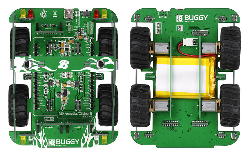
This example demonstrates wireless Buggy control, using clicker2 for STM32/PIC32/PIC18FJ/FT900, BLE-P click board and Android smart phone.

No Abuse Reported

Do you want to subscribe in order to receive notifications regarding "Buggy example" changes.

Do you want to unsubscribe in order to stop receiving notifications regarding "Buggy example" changes.

Do you want to report abuse regarding "Buggy example".

  • Information
  • Comments (3)

Example Blog

Buggy - Example

Buggy - Example

Front and back side appearance of the Buggy.

View full image

If you want to take your Buggy for a spin as soon as possible, attach BLE P click to one of the three mikroBUS sockets, and install the free Buggy Android app on your nearest Bluetooth Low Energy compatible smartphone or tablet. The source code is available for free. Use it to tailor the app for any number of specific uses you intended for the Buggy. Examples are written for :
 - Clicker 2 Board for STM32 - STM32F407VG
 - Clicker 2 Board for PIC18FJ - PIC18F87J50
 - Clicker 2 Board for PIC32MX - PIC32MX460F512L

 - Clicker 2 Board for FT900 - FT900
 

Buggy schematic

Buggy schematic

The schematics of Buggy.

View full image

ALSO FROM THIS AUTHOR

DIGI IO Click

0

DIGI I/O Click is a compact add-on board for flexible industrial digital input and output control. This board features the MAX14906, a quad-channel industrial digital input/output IC from Analog Devices, compliant with IEC 61131-2 standard. Each channel can be individually configured as a high-side switch, push-pull driver, or digital input, supporting various operating modes with current limiting up to 1.2A and fast signal transmission. The board supports 24V operation by default, with options for individual channel power configuration, and includes built-in diagnostics like overvoltage and undervoltage detection, thermal overload, and wire-break detection. DIGI I/O Click is ideal for industrial automation, motor control systems, PLCs, and Distributed Control Systems (DCS).

[Learn More]

TouchKey click

5

Touchkey click has four capacitive pads powered by TTP224, a touchpad detector IC. Capacitive buttons like these can be toggled even when placed under a layer of glass or paper. The example demonstrates the usage of TouchKey Click

[Learn More]

OLED Switch click

1

This board has a module that combines a button and a full color organic LED display, plus input/output screw terminals for connecting external electronics. The mechanical button itself is nicely built, with a translucent black housing. When pressed, it gives satisfying tactile feedback.

[Learn More]