We strongly encourage users to use Package manager for sharing their code on Libstock website, because it boosts your efficiency and leaves the end user with no room for error. [more info]

Rating:
Author: Andrew Hazelton
Last Updated: 2017-10-12
Package Version: 1.2.0.0
Example: 1.0.0.0
Category: Timers (Real time clock)
Downloaded: 2628 times
Followed by: 2 users
License: MIT license
This is an example of how to use the STM32F407VG internal Real Time Clock (RTC) and Calender module with external LSE oscillator to be 32.768 kHz.
Do you want to subscribe in order to receive notifications regarding "STM32F4 Internal RTC and Calender" changes.
Do you want to unsubscribe in order to stop receiving notifications regarding "STM32F4 Internal RTC and Calender" changes.
Do you want to report abuse regarding "STM32F4 Internal RTC and Calender".
| DOWNLOAD LINK | RELATED COMPILER | CONTAINS |
|---|---|---|
| 1439203913_stm32f4_internal_mikroc_arm.zip [503.20KB] | mikroC PRO for ARM |
|

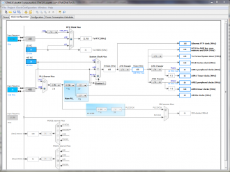
STM32F4 Internal RTC & Calender Module Diagram
View full image
This is a screen capture from the STM32CubeMX software provided free from st.com that visually shown the internal system clock lines an Prescaler values. It makes it much easier to understand than trying to piece it all together from the datasheet.
View full imageThis is an example of how to use the STM32F407VG internal Real Time Clock (RTC) and Calender module with external LSE oscillator to be 32.768 kHz.
The mE USART Terminal is used to print out the RTC and Calender values and status messages. Turn on USB UART B. Turn ON SW12.3 SW12.4 (Board: EasyMx PRO v7 for STM32 ARM).
Connecting a USB cable between your PC and USB UART B on board will create a virtual COM port on your PC which can then be accessed via the mE USART Terminal within your mE compiler.
Use the “Computer_Brd_Chip_168MHz.cfgsch” file in the attached for internal MCU configuration. The image above is a visual depiction of this configuration file setup. This setup will insure that the STM32F407VG is running at its maximum speed.
For full details on STM32F4 internal modules see RM0090 ST Reference Manual from st.com.
RTC_Init ( … )
RTC_SetTime ( … )
RTC_SetDate ( … )
RTC_GetSubSeconds ( … )
RTC_GetTime ( … )
RTC_GetDate ( … ) // Printing values across to the mE USART Terminal
RTC_PrintTime ( … )
RTC_PrintDate ( … )
Print_Sub_Secs ( … )
*****************************************************************************************
Version 1.2.0.0 - 10th Aug 2015
Added Calibrate_RTC_Crystal function.
Changed RTC_SetTime function.
Changed RTC_Init function.
Made minor improvements.