TOP Contributors

  1. MIKROE (2784 codes)
  2. Alcides Ramos (405 codes)
  3. Shawon Shahryiar (307 codes)
  4. jm_palomino (133 codes)
  5. Bugz Bensce (97 codes)
  6. S P (73 codes)
  7. dany (71 codes)
  8. MikroBUS.NET Team (35 codes)
  9. NART SCHINACKOW (34 codes)
  10. Armstrong Subero (27 codes)

Most Downloaded

  1. Timer Calculator (141679 times)
  2. FAT32 Library (74728 times)
  3. Network Ethernet Library (59203 times)
  4. USB Device Library (49213 times)
  5. Network WiFi Library (44988 times)
  6. FT800 Library (44517 times)
  7. GSM click (31195 times)
  8. mikroSDK (30081 times)
  9. microSD click (27577 times)
  10. PID Library (27537 times)
Libstock prefers package manager

Package Manager

We strongly encourage users to use Package manager for sharing their code on Libstock website, because it boosts your efficiency and leaves the end user with no room for error. [more info]

< Back
Project

8-Digit 7-Segment LED Display in a mikroBUS Format

Rating:

5

Author: Val Gretchev

Last Updated: 2016-02-17

Package Version: 1.0.0.0

Category: Graphics & LCD

Downloaded: 481 times

Followed by: 3 users

License: MIT license  

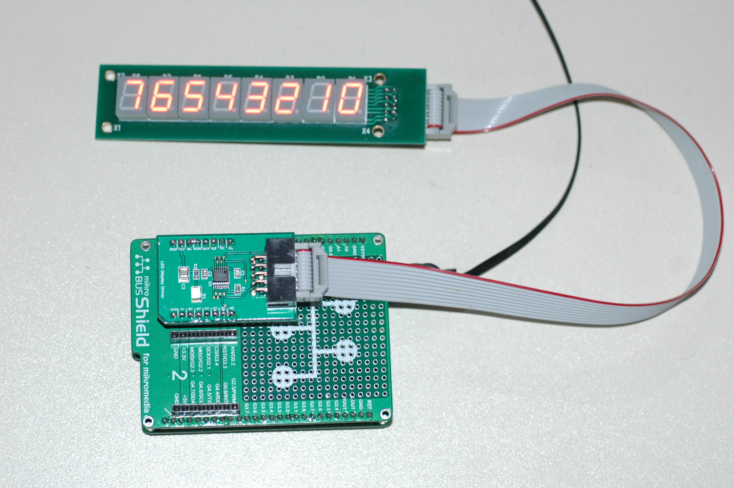
Sometimes you just need a long numeric LED display with up to 8 digits. This example provides manufacturing files to construct two PCBs. One with the appropriate driver circuits on a mikroBUS format board and the other with a row of LED modules that can be mounted remotely.

No Abuse Reported

Do you want to subscribe in order to receive notifications regarding "8-Digit 7-Segment LED Display in a mikroBUS Format" changes.

Do you want to unsubscribe in order to stop receiving notifications regarding "8-Digit 7-Segment LED Display in a mikroBUS Format" changes.

Do you want to report abuse regarding "8-Digit 7-Segment LED Display in a mikroBUS Format".

  • Information
  • Comments (0)
DOWNLOAD LINK RELATED COMPILER CONTAINS
mikroC PRO for ARM
  • lib
  • src
  • exa
  • hlp
  • hex
  • sch
  • pcb
  • doc

Project Blog

Working Prototype

Working Prototype

The driver module resides on a mikroBUS format board. The display is on a second board that can be mounted remotely

View full image

ALSO FROM THIS AUTHOR

Mikromedia Plus for STM32 with Shield and GPS Click L10 Board.

0

This example uses the GPS click L10 board in slot 2 of the shield and communicates with it through UART2. Commands and messages are available using UART6-to-USB circuit on the shield board. The USB-HID Bootloader is used for loading the code. However, you can use mikroProg programmer if you prefer.

[Learn More]

Using WiFi to set RTC on Tiva board

0

Another example of setting the real-time-clock with data obtained from an Internet time server using the external CC3000 chip on the Tiva board. The FT232 chip on the shield board is used for diagnostic messages.

[Learn More]

Delphi 7 example for testing the GPS L10 Click Board

0

The simplest way to test a GPS click board is to connect it to a PC by means of the built-in USB port. This program, written for Delphi 7, can be used to monitor the click board output messages. Use Disable Auto Output to stop automatic transmissions; Verbose mode to interpret fields.

[Learn More]