TOP Contributors

  1. MIKROE (2642 codes)
  2. Alcides Ramos (347 codes)
  3. Shawon Shahryiar (307 codes)
  4. jm_palomino (112 codes)
  5. Chisanga Mumba (90 codes)
  6. S P (73 codes)
  7. dany (71 codes)
  8. MikroBUS.NET Team (35 codes)
  9. NART SCHINACKOW (34 codes)
  10. Armstrong Subero (27 codes)

Most Downloaded

  1. Timer Calculator (136223 times)
  2. FAT32 Library (69492 times)
  3. Network Ethernet Library (55710 times)
  4. USB Device Library (45994 times)
  5. Network WiFi Library (41639 times)
  6. FT800 Library (40801 times)
  7. GSM click (28789 times)
  8. PID Library (26332 times)
  9. mikroSDK (26059 times)
  10. microSD click (25145 times)
Libstock prefers package manager

Package Manager

We strongly encourage users to use Package manager for sharing their code on Libstock website, because it boosts your efficiency and leaves the end user with no room for error. [more info]

< Back
Project

RC motor control Cmos output version

Rating:

9

Author: brian phillips

Last Updated: 2016-02-18

Package Version: 1.0.0.0

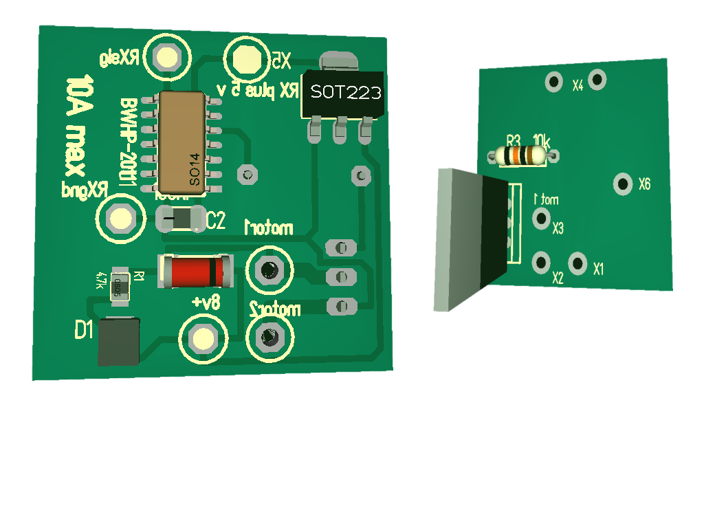
Category: Motor Control

Downloaded: 2481 times

Followed by: 3 users

License: MIT license  

An improved higher power version of my previous circuit. Software is basically the same as previous.

No Abuse Reported

Do you want to subscribe in order to receive notifications regarding "RC motor control Cmos output version" changes.

Do you want to unsubscribe in order to stop receiving notifications regarding "RC motor control Cmos output version" changes.

Do you want to report abuse regarding "RC motor control Cmos output version".

  • Information
  • Comments (0)
DOWNLOAD LINK RELATED COMPILER CONTAINS
mikroBasic PRO for PIC
  • lib
  • src
  • exa
  • hlp
  • hex
  • sch
  • pcb
  • doc

Project Blog

An updated version of the previous RC boat motor driver, this time with schematics and PCB design for Cmos output.
Slight changes made to software to improve performance, and to correct a smal bug that could stop the PWM working but in practice did not !
The software was written for Pic 16F684 but can easily be adapted for other pics with PWM. Osc. was configured for 4 Mhz.
A Targa PCB file is included, containing the circuit and PCB. The PCB is designed as a singlesided board with surface mount components (30 mm X 30 mm), One can of course change the design for throughhole boards.

Note: the board includes a LDO 5 Volt regulator as a BEC for the receiver.
The motor driver has a maximum current capability of 9 Ampere (with appropriate heatsinking).
If double sided PCB is used and the Cmos transistor heatsinked on the unused copper side, then the unit is quite capable for sourcing over 1 ampere which is adequate foe most 12 volt model boar motors. As stated a higher current can be achieved with extra heatsinking. As I have not carried out measurements with extended heat sinking, I would advise that if you require the extra capacity that you add a heatsink and then gradually increase the current to establish if the cmos reamins within reasonable temperatures. Do not fully load the circuit until you have made this test or you will surely destroy the Cmos.
Important addition in case you don't spot it: If you use double sided board, then make sure you use a drill etc. to clear around the component leg holes on the copper side where the resistor and cmos are mounted , or the legs might short out! 

PCB

PCB

Graphic of the PCB and components viewed from both sides

View full image

ALSO FROM THIS AUTHOR

RC pulse driving DC motor for model boat etc.

7

The software checks the pulse length and then sets the PWM output to suit. The PWM output is then used to drive a DC motor via a transistor or FET of suitable power rating. A port read was used to detect the pulse width and this method is not very accurate, however it is sufficiently accurate for this application, and works very well for my models.

[Learn More]

RC two channel selector.

9

This project selects an output for a 1Ms pulse or for a 2 MS pulse . This can be used to drive a model motor reverser or other similar application.'this routine was created to provide simple switching outputs from A Targa PCB & schematic file is included

[Learn More]