
We strongly encourage users to use Package manager for sharing their code on Libstock website, because it boosts your efficiency and leaves the end user with no room for error. [more info]

Rating:
Author: dany
Last Updated: 2016-02-18
Package Version: 1.0.0.0
Category: Power supply
Downloaded: 1690 times
Followed by: 3 users
License: MIT license
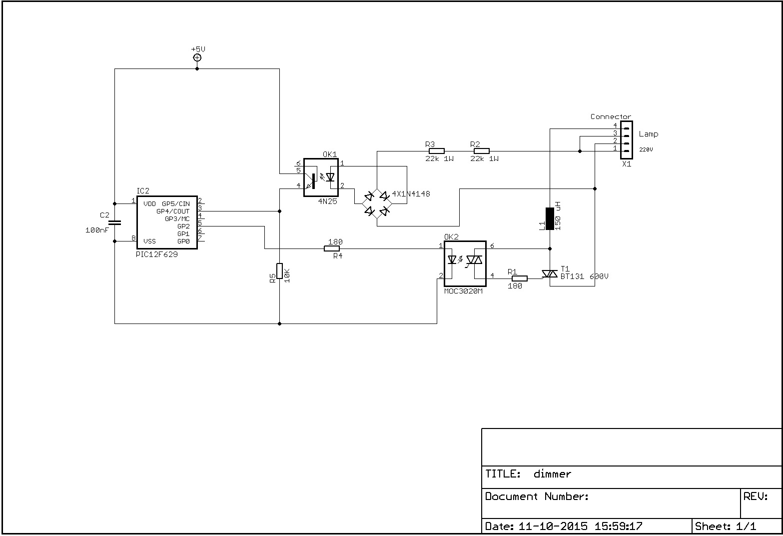
Simple galvanic isolated dimmer (with triac phase control) for 230V AC.
Do you want to subscribe in order to receive notifications regarding "AC Dimmer, 230V" changes.
Do you want to unsubscribe in order to stop receiving notifications regarding "AC Dimmer, 230V" changes.
Do you want to report abuse regarding "AC Dimmer, 230V".
| DOWNLOAD LINK | RELATED COMPILER | CONTAINS |
|---|---|---|
| 1444573020_ac_dimmer__230v_mikropascal_pic.zip [68.97KB] | mikroPascal PRO for PIC |
|
This is a very simple dimmer with a triac output (phase control). It uses timer0 to do the timing.
The control part (here a P12F629) is competely isolated from the 230V mains supply:
- the zero crossing detector contains an optocoupler (4N25 or similar),
- the drive of the triac also contains an opto coupler (MOC3025 or similar). Be aware: the latter optocoupler should NOT have a zero cross detection!
The 5V power supply is not drawn in the schematic.
The ignition angle can be set in the example by setting the value of Tmr0 at the end of the zero crossing detection. The example uses only these 3 values, see the comments below:
Case Step of
0: Tmr0 := 0; // never ignite triac (delay > 10 ms)
1: Tmr0 := 140; // low value = long delay = late ignition = low power
2: Tmr0 := 175; // average power
3: Tmr0 := 250; // high value = short delay = high power
end;

The 230V mains is connected between pins 1 and 2 of the connector, the load (e.g. an incandescent lamp) is connected between pins 3 and 4.
2015-10-10: the circuit diagram has been adapted to the correct (with galvanic separation between the grid and the PIC) one.


