TOP Contributors

  1. MIKROE (2784 codes)
  2. Alcides Ramos (405 codes)
  3. Shawon Shahryiar (307 codes)
  4. jm_palomino (133 codes)
  5. Bugz Bensce (97 codes)
  6. S P (73 codes)
  7. dany (71 codes)
  8. MikroBUS.NET Team (35 codes)
  9. NART SCHINACKOW (34 codes)
  10. Armstrong Subero (27 codes)

Most Downloaded

  1. Timer Calculator (141481 times)
  2. FAT32 Library (74335 times)
  3. Network Ethernet Library (58869 times)
  4. USB Device Library (48921 times)
  5. Network WiFi Library (44698 times)
  6. FT800 Library (44227 times)
  7. GSM click (30937 times)
  8. mikroSDK (29817 times)
  9. PID Library (27423 times)
  10. microSD click (27375 times)
Libstock prefers package manager

Package Manager

We strongly encourage users to use Package manager for sharing their code on Libstock website, because it boosts your efficiency and leaves the end user with no room for error. [more info]

< Back
mikroSDK Library

ADC3 Click

Rating:

7

Author: MIKROE

Last Updated: 2019-03-26

Package Version: 1.0.1.1

mikroSDK Library: 1.0.0.0

Category: ADC

Downloaded: 6400 times

Followed by: 3 users

License: MIT license  

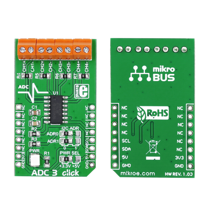
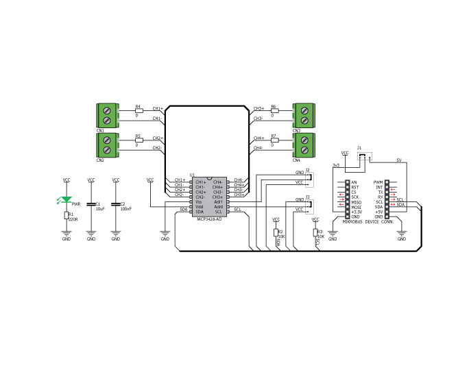
ADC3 click carries Microchip’s MCP3428 16-bit multichannel analog-to-digital converter. The click has four pairs of screw terminals onboard, letting you access the chip’s four differential input channels. ADC3 click communicates with the target MCU through mikroBUS I2C pins (SCL, SDA). It is designed to use either a 3.3V or 5V power supply.

No Abuse Reported

Do you want to subscribe in order to receive notifications regarding "ADC3 Click" changes.

Do you want to unsubscribe in order to stop receiving notifications regarding "ADC3 Click" changes.

Do you want to report abuse regarding "ADC3 Click".

  • mikroSDK Library 2.0.0.0
  • Comments (5)
DOWNLOAD LINK RELATED COMPILER CONTAINS
mikroBasic PRO for ARM
  • lib
  • src
  • exa
  • hlp
  • hex
  • sch
  • pcb
  • doc
mikroBasic PRO for AVR
  • lib
  • src
  • exa
  • hlp
  • hex
  • sch
  • pcb
  • doc
mikroBasic PRO for dsPIC30/33 & PIC24
  • lib
  • src
  • exa
  • hlp
  • hex
  • sch
  • pcb
  • doc
mikroBasic PRO for FT90x
  • lib
  • src
  • exa
  • hlp
  • hex
  • sch
  • pcb
  • doc
mikroBasic PRO for PIC
  • lib
  • src
  • exa
  • hlp
  • hex
  • sch
  • pcb
  • doc
mikroBasic PRO for PIC32
  • lib
  • src
  • exa
  • hlp
  • hex
  • sch
  • pcb
  • doc
mikroC PRO for ARM
  • lib
  • src
  • exa
  • hlp
  • hex
  • sch
  • pcb
  • doc
mikroC PRO for AVR
  • lib
  • src
  • exa
  • hlp
  • hex
  • sch
  • pcb
  • doc
mikroC PRO for dsPIC30/33 & PIC24
  • lib
  • src
  • exa
  • hlp
  • hex
  • sch
  • pcb
  • doc
mikroC PRO for FT90x
  • lib
  • src
  • exa
  • hlp
  • hex
  • sch
  • pcb
  • doc
mikroC PRO for PIC
  • lib
  • src
  • exa
  • hlp
  • hex
  • sch
  • pcb
  • doc
mikroC PRO for PIC32
  • lib
  • src
  • exa
  • hlp
  • hex
  • sch
  • pcb
  • doc
mikroPascal PRO for ARM
  • lib
  • src
  • exa
  • hlp
  • hex
  • sch
  • pcb
  • doc
mikroPascal PRO for AVR
  • lib
  • src
  • exa
  • hlp
  • hex
  • sch
  • pcb
  • doc
mikroPascal PRO for dsPIC30/33 & PIC24
  • lib
  • src
  • exa
  • hlp
  • hex
  • sch
  • pcb
  • doc
mikroPascal PRO for FT90x
  • lib
  • src
  • exa
  • hlp
  • hex
  • sch
  • pcb
  • doc
mikroPascal PRO for PIC
  • lib
  • src
  • exa
  • hlp
  • hex
  • sch
  • pcb
  • doc
mikroPascal PRO for PIC32
  • lib
  • src
  • exa
  • hlp
  • hex
  • sch
  • pcb
  • doc

mikroSDK Library Blog

ADC3 Click board

ADC3 Click board

Front and back side appearance of the ADC3 Click Board.

View full image

Library Description

The library covers all the necessary functions that enables the usage of the ADC 3 click board.
It initializes and defines the I2C driver and drivers that offer a choice for reading digital
data from all four channels seperatly or all together.

Key functions:

  • uint16_t adc3_readData( uint8_t config, uint8_t resolution ); -  Function is used to read digitaly converted data from any of the 4 channels.
  • void adc3_reset();-   Function is used to initiate general call reset.
  • void adc3_conversion(); -   Function is used to initiate general call conversion.

Examples Description

The application is composed of three sections:

  • System Initialization - Initializes I2C and LOG structures.
  • Application Initialization - Initalizes I2C driver, resets the device and makes an initial log.
  • Application Task - (code snippet) This is an example that shows the capabilities of the ADC 3 click by taking measurements from all four channel simultaneously.
void applicationTask()
{
    configuration1 = _ADC3_PGA_GAIN_X1 | _ADC3_SAMPLE_RATE_16 | _ADC3_CONTINOUS_ADDR | _ADC3_SELECT_CHANNEL_1;
    readVal = adc3_readData( configuration1, _ADC3_SAMPLE_RATE_16 );
    Delay_ms( 100 );
    IntToStr( readVal, txtLog );
    Ltrim( txtLog );
    mikrobus_logWrite( "Channel 1 : ", _LOG_TEXT );
    mikrobus_logWrite( txtLog, _LOG_LINE );

    configuration2 = _ADC3_PGA_GAIN_X1 | _ADC3_SAMPLE_RATE_16 | _ADC3_CONTINOUS_ADDR | _ADC3_SELECT_CHANNEL_2;
    readVal = adc3_readData( configuration2, _ADC3_SAMPLE_RATE_16 );
    Delay_ms( 100 );
    IntToStr( readVal, txtLog );
    Ltrim( txtLog );
    mikrobus_logWrite( "Channel 2 : ", _LOG_TEXT );
    mikrobus_logWrite( txtLog, _LOG_LINE );

    configuration3 = _ADC3_PGA_GAIN_X1 | _ADC3_SAMPLE_RATE_16 | _ADC3_CONTINOUS_ADDR | _ADC3_SELECT_CHANNEL_3;
    readVal = adc3_readData( configuration3, _ADC3_SAMPLE_RATE_16 );
    Delay_ms( 100 );
    IntToStr( readVal, txtLog );
    Ltrim( txtLog );
    mikrobus_logWrite( "Channel 3 : ", _LOG_TEXT );
    mikrobus_logWrite( txtLog, _LOG_LINE );

    configuration4 = _ADC3_PGA_GAIN_X1 | _ADC3_SAMPLE_RATE_16 | _ADC3_CONTINOUS_ADDR | _ADC3_SELECT_CHANNEL_4;
    readVal = adc3_readData( configuration4, _ADC3_SAMPLE_RATE_16 );
    Delay_ms( 100 );
    IntToStr( readVal, txtLog );
    Ltrim( txtLog );
    mikrobus_logWrite( "Channel 4 : ", _LOG_TEXT );
    mikrobus_logWrite( txtLog, _LOG_LINE );

    mikrobus_logWrite( "------------------", _LOG_LINE );
    Delay_ms( 1000 );
}  

Other mikroE Libraries used in the example:

  • I2C
  • UART
  • Conversions

Additional notes and informations

Depending on the development board you are using, you may need USB UART clickUSB UART 2 click or RS232 click to connect to your PC, for development systems with no UART to USB interface available on the board. The terminal available in all MikroElektronika compilers, or any other terminal application of your choice, can be used to read the message

ADC3 Click Board schematics

ADC3 Click Board schematics

Schematics of the ADC3 Click Board.

View full image

ALSO FROM THIS AUTHOR

EasyPIC6 Examples

5

Examples for EasyPIC 6 development system

[Learn More]

TFmini Click

0

TFmini Click is an adapter Click board™ used to interface a compatible ToF (Time of Flight) LiDAR sensor with the host MCU. This board features one four positions 1.25mm connector suitable for a TFmini LiDAR module (TFmini Plus and TFmini-S) specially made to measure an object's distance. Depending on the used LiDAR module, it is possible to achieve different measurement ranges and the use of a different serial interface, such as the UART or I2C. This Click board™ is suitable for various industrial environments like pedestrian detection, vehicle testing, and altitude.

[Learn More]

DC Motor 15 click

5

DC Motor 15 Click is a compact add-on board that contains a motor driver with current sense and regulation. This board features the DRV8874, an integrated motor driver with N-channel H-bridge, charge pump, current sensing, and adjustment from Texas Instruments.

[Learn More]