TOP Contributors

  1. MIKROE (2742 codes)
  2. Alcides Ramos (370 codes)
  3. Shawon Shahryiar (307 codes)
  4. jm_palomino (118 codes)
  5. Bugz Bensce (90 codes)
  6. S P (73 codes)
  7. dany (71 codes)
  8. MikroBUS.NET Team (35 codes)
  9. NART SCHINACKOW (34 codes)
  10. Armstrong Subero (27 codes)

Most Downloaded

  1. Timer Calculator (138845 times)
  2. FAT32 Library (71474 times)
  3. Network Ethernet Library (56907 times)
  4. USB Device Library (47260 times)
  5. Network WiFi Library (42944 times)
  6. FT800 Library (42273 times)
  7. GSM click (29718 times)
  8. mikroSDK (27646 times)
  9. PID Library (26826 times)
  10. microSD click (26081 times)
Libstock prefers package manager

Package Manager

We strongly encourage users to use Package manager for sharing their code on Libstock website, because it boosts your efficiency and leaves the end user with no room for error. [more info]

< Back
Project

Clapper Switch Project

Rating:

0

Author: NART SCHINACKOW

Last Updated: 2011-10-03

Package Version: 1.0.0.0

Category: Other Codes

Downloaded: 958 times

Not followed.

License: MIT license  

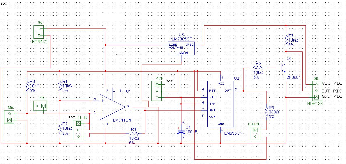
This a simple clapper switch circuit consisted of : op-amp,555,transistor,and a couple of resistors.
the schematic is included in the file and has the header for connecting it to a pic microcontroller.
all you need is a simple program to control the timing of the output wave of the 555.

No Abuse Reported

Do you want to subscribe in order to receive notifications regarding "Clapper Switch Project" changes.

Do you want to unsubscribe in order to stop receiving notifications regarding "Clapper Switch Project" changes.

Do you want to report abuse regarding "Clapper Switch Project".

  • Information
  • Comments (0)
DOWNLOAD LINK RELATED COMPILER CONTAINS
mikroC PRO for PIC
  • lib
  • src
  • exa
  • hlp
  • hex
  • sch
  • pcb
  • doc

Project Blog

Clapper Schematic

Clapper Schematic

Circuit Of The Clapper Switch

View full image

CIRCUIT DESCRIPTION

The circuit is consisted of two main parts :

LM741 OP-AMP:
This is responsible for amplifying the microphone signals and feed them to the 555 pin2 (TRIGGER PIN)

555 timer IC:
It is The Timing stage, when a signal is reached at pin2 the 555 will output a square wave at pin3 which length is defined by the potentiometer .
the 555 is configured as a monostable.

Note: This Project May Be Optimized And Changed Any Time So Stay Tuned

CHECK OUT MY WEBSITE FOR MORE CODES AND PROJECTS

ALSO FROM THIS AUTHOR

DS1307 Wrapped Rtc Library With Format

5

This is a structured based DS1307 time library, copy the 2 files into your project folder and include Time.h in your source code.

[Learn More]

NETDUINO PLUS HTTP WEBSERVER

0

Netduino plus is an open source hardware and software board, specs could be found at http://www.netduino.com/netduinoplus/specs.htm it uses microsoft .net micro frame work uses Atmel 32-bit microcontroller, Speed: 48MHz, ARM7 This Project demonstrates an http web server

[Learn More]

NS73M FM TRANSMITTER LIBRARY

0

Simple library for the NS73M FM transmitter, the library contains functions to communicate with the module, all you need is a PIC and the module which can be found at http://www.sparkfun.com/products/8482 , a simple wire of 31 inch long and you are ready to go. just copy the two files into your project folder and include "NS73M.h".

[Learn More]