TOP Contributors

  1. MIKROE (2784 codes)
  2. Alcides Ramos (405 codes)
  3. Shawon Shahryiar (307 codes)
  4. jm_palomino (133 codes)
  5. Bugz Bensce (97 codes)
  6. S P (73 codes)
  7. dany (71 codes)
  8. MikroBUS.NET Team (35 codes)
  9. NART SCHINACKOW (34 codes)
  10. Armstrong Subero (27 codes)

Most Downloaded

  1. Timer Calculator (142097 times)
  2. FAT32 Library (75363 times)
  3. Network Ethernet Library (59524 times)
  4. USB Device Library (49549 times)
  5. Network WiFi Library (45355 times)
  6. FT800 Library (44975 times)
  7. GSM click (31485 times)
  8. mikroSDK (30544 times)
  9. microSD click (27865 times)
  10. PID Library (27631 times)
Libstock prefers package manager

Package Manager

We strongly encourage users to use Package manager for sharing their code on Libstock website, because it boosts your efficiency and leaves the end user with no room for error. [more info]

< Back
mikroSDK Library

ADAC click

Rating:

6

Author: MIKROE

Last Updated: 2019-07-29

Package Version: 1.0.0.1

mikroSDK Library: 1.0.0.0

Category: ADC-DAC

Downloaded: 6204 times

Not followed.

License: MIT license  

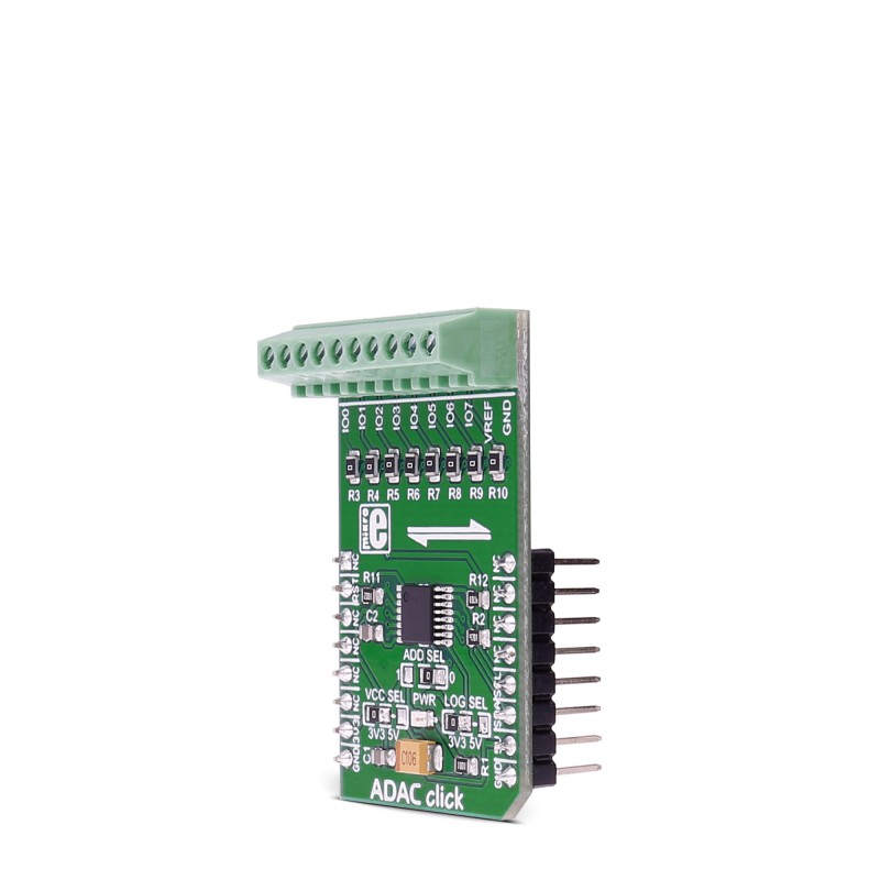
ADAC click is an 8-channel 12bit ADC, DAC and GPIO converter. The click is designed to run on either 3.3V or 5V power supply. ADAC click communicates with the target microcontroller over I2C interface, with additional functionality provided by the RST pin on the mikroBUSâ„¢ line.

No Abuse Reported

Do you want to subscribe in order to receive notifications regarding "ADAC click" changes.

Do you want to unsubscribe in order to stop receiving notifications regarding "ADAC click" changes.

Do you want to report abuse regarding "ADAC click".

  • mikroSDK Library 2.0.0.0
  • Comments (0)
DOWNLOAD LINK RELATED COMPILER CONTAINS
mikroBasic PRO for ARM
  • lib
  • src
  • exa
  • hlp
  • hex
  • sch
  • pcb
  • doc
mikroBasic PRO for AVR
  • lib
  • src
  • exa
  • hlp
  • hex
  • sch
  • pcb
  • doc
mikroBasic PRO for dsPIC30/33 & PIC24
  • lib
  • src
  • exa
  • hlp
  • hex
  • sch
  • pcb
  • doc
mikroBasic PRO for FT90x
  • lib
  • src
  • exa
  • hlp
  • hex
  • sch
  • pcb
  • doc
mikroBasic PRO for PIC
  • lib
  • src
  • exa
  • hlp
  • hex
  • sch
  • pcb
  • doc
mikroBasic PRO for PIC32
  • lib
  • src
  • exa
  • hlp
  • hex
  • sch
  • pcb
  • doc
mikroC PRO for ARM
  • lib
  • src
  • exa
  • hlp
  • hex
  • sch
  • pcb
  • doc
mikroC PRO for AVR
  • lib
  • src
  • exa
  • hlp
  • hex
  • sch
  • pcb
  • doc
mikroC PRO for dsPIC30/33 & PIC24
  • lib
  • src
  • exa
  • hlp
  • hex
  • sch
  • pcb
  • doc
mikroC PRO for FT90x
  • lib
  • src
  • exa
  • hlp
  • hex
  • sch
  • pcb
  • doc
mikroC PRO for PIC
  • lib
  • src
  • exa
  • hlp
  • hex
  • sch
  • pcb
  • doc
mikroC PRO for PIC32
  • lib
  • src
  • exa
  • hlp
  • hex
  • sch
  • pcb
  • doc
mikroPascal PRO for ARM
  • lib
  • src
  • exa
  • hlp
  • hex
  • sch
  • pcb
  • doc
mikroPascal PRO for AVR
  • lib
  • src
  • exa
  • hlp
  • hex
  • sch
  • pcb
  • doc
mikroPascal PRO for dsPIC30/33 & PIC24
  • lib
  • src
  • exa
  • hlp
  • hex
  • sch
  • pcb
  • doc
mikroPascal PRO for FT90x
  • lib
  • src
  • exa
  • hlp
  • hex
  • sch
  • pcb
  • doc
mikroPascal PRO for PIC
  • lib
  • src
  • exa
  • hlp
  • hex
  • sch
  • pcb
  • doc
mikroC PRO for PIC32
  • lib
  • src
  • exa
  • hlp
  • hex
  • sch
  • pcb
  • doc

mikroSDK Library Blog

ADAC click

ADAC click

Native view of the ADAC click board.

View full image

Library Description

The library covers all the necessary functions that enables the usage of the ADAC click board.
It initializes and defines the I2C driver and drivers that offer a choice for reading and writing DAC
data from and to all eight channels and reading ADC data from all eight channels. User also has diferent 
functions that allow diferent settings at his disposal.

Key functions:

  • void adac_setConfiguration( uint8_t ptByte, uint8_t msbData, uint8_t lsbData ) - Function is used to configure the device to users needs.
  • void adac_writeDACData( uint8_t wrChann, uint16_t wrData ) - Function is used to write 16-bit data to the designated channel.
  • uint16_t adac_readADC( uint8_t *IOChannel ) - Function is used to read ADC value from any of the channels.

Examples description

The application is composed of three sections :

  • System Initialization - Initializes GPIO, I2C and LOG structures, set RST pin as output.
  • Application Initialization - Initalizes I2C driver, sets up default configuration and makes an initial log.
  • Application Task - This is an example that shows some of the functions that ADAC click has. It demonstrates Write DAC and read ADC functions and settings.
void applicationTask()
{
    uint16_t i;
    uint16_t ADCValue;
    uint8_t channel;
    char logTxt[ 50 ];

mikrobus_logWrite( " Write DAC demonstration  ", _LOG_LINE );
    adac_setConfiguration( _ADAC_DAC_CONFIG, _ADAC_NO_OP, _ADAC_IO3 );
    Delay_ms( 100 );
    for ( i = 0; i < 0XFF; i += 4 )
    {
        adac_writeDAC( _ADAC_PB_PIN3, i / 0x100, i % 0x100 );
        Delay_ms( 10 );
        mikrobus_logWrite( " * ", _LOG_LINE );

            }
    mikrobus_logWrite( " Demonstration finished  ", _LOG_LINE );
    mikrobus_logWrite( "-------------------------", _LOG_LINE );
    Delay_ms( 1000 );
        mikrobus_logWrite( " Read ADC demonstration  ", _LOG_LINE );
    adac_setConfiguration( _ADAC_ADC_CONFIG, _ADAC_NO_OP, _ADAC_IO4 );
    Delay_ms( 100 );
    adac_setConfiguration( _ADAC_ADC_SEQUENCE, _ADAC_SEQUENCE_ON, _ADAC_IO4 );
    for ( i = 0; i < 10; i++ )
    {
        ADCValue = adac_readADC( &channel );
        ShortToStr( channel, logTxt );
        Ltrim( logTxt );
        mikrobus_logWrite( "ADC value on channel ", _LOG_TEXT );
        mikrobus_logWrite( logTxt, _LOG_TEXT );
        mikrobus_logWrite( " is : ", _LOG_TEXT );
        WordToStr( ADCValue, logTxt );
        Ltrim( logTxt );
        mikrobus_logWrite( logTxt, _LOG_LINE );
        Delay_ms( 2000 );
    }
    mikrobus_logWrite( " Demonstration finished  ", _LOG_LINE );
    mikrobus_logWrite( "-------------------------", _LOG_LINE );
    Delay_ms( 1000 );
}

Other mikroE Libraries used in the example:

  • I2C
  • UART
  • Conversions

Additional notes and informations

Depending on the development board you are using, you may need USB UART clickUSB UART 2 click or RS232 click to connect to your PC, for development systems with no UART to USB interface available on the board. The terminal available in all MikroElektronika compilers, or any other terminal application of your choice, can be used to read the message.

ALSO FROM THIS AUTHOR

LED Driver 17 Click

0

LED Driver 17 Click is a compact add-on board that offers a simple solution for controlling multiple LEDs, making it an ideal choice for various applications. This board features the LTR3755, a highly efficient DC/DC controller from Analog Devices that operates as a constant-current source. It can easily drive high current LEDs and features onboard low-side external N-channel power MOSFETs driven from an internal regulated supply. The LED Driver 17 Click is capable of stable operation over a wide supply range and offers several LED protection features, including overvoltage and overcurrent protection. Additionally, the frequency adjust pin allows users to program the switching frequency from 100kHz to 1MHz, optimizing efficiency and performance.

[Learn More]

Mikromedia 5 for Kinetis Capacitive

0

This project contains example for testing modules on Mikromedia 5 for Kinetis Capacitive.

[Learn More]

Piezo Accel 2 50g Click

0

Piezo Accel 2 Click - 50g is a compact add-on board for precise vibration and motion monitoring in condition-based maintenance applications. This board features the 830M1-0050, a triaxial piezoelectric accelerometer from TE Connectivity, capable of detecting motion and acceleration along all three axes (X, Y, Z). The 830M1-0050 offers a ±50g range with a sensitivity of 25mV/g, providing reliable and accurate analog voltage outputs. It integrates a built-in RTD temperature sensor for simultaneous vibration and temperature monitoring, and the onboard MCP3562R 24-bit ADC converts these signals into high-resolution digital data. Communication is made through an SPI interface with additional interrupt and clock functionality for easy integration with a host MCU.

[Learn More]