TOP Contributors

  1. MIKROE (2784 codes)
  2. Alcides Ramos (387 codes)
  3. Shawon Shahryiar (307 codes)
  4. jm_palomino (120 codes)
  5. Bugz Bensce (97 codes)
  6. S P (73 codes)
  7. dany (71 codes)
  8. MikroBUS.NET Team (35 codes)
  9. NART SCHINACKOW (34 codes)
  10. Armstrong Subero (27 codes)

Most Downloaded

  1. Timer Calculator (140166 times)
  2. FAT32 Library (72621 times)
  3. Network Ethernet Library (57641 times)
  4. USB Device Library (47953 times)
  5. Network WiFi Library (43553 times)
  6. FT800 Library (42942 times)
  7. GSM click (30140 times)
  8. mikroSDK (28668 times)
  9. PID Library (27055 times)
  10. microSD click (26552 times)
Libstock prefers package manager

Package Manager

We strongly encourage users to use Package manager for sharing their code on Libstock website, because it boosts your efficiency and leaves the end user with no room for error. [more info]

< Back
mikroSDK Library

RS485 2 click

Rating:

6

Author: MIKROE

Last Updated: 2018-06-14

Package Version: 1.0.0.2

mikroSDK Library: 1.0.0.0

Category: RS485

Downloaded: 9613 times

Not followed.

License: MIT license  

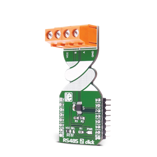
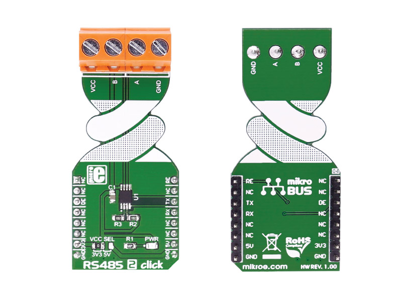
RS485 2 click is an RS422/485 transceiver Click board, which can be used as an interface between the TTL level UART and the RS422/485 communication bus.

No Abuse Reported

Do you want to subscribe in order to receive notifications regarding "RS485 2 click" changes.

Do you want to unsubscribe in order to stop receiving notifications regarding "RS485 2 click" changes.

Do you want to report abuse regarding "RS485 2 click".

  • mikroSDK Library 2.0.0.0
  • Comments (1)
DOWNLOAD LINK RELATED COMPILER CONTAINS
mikroBasic PRO for ARM
  • lib
  • src
  • exa
  • hlp
  • hex
  • sch
  • pcb
  • doc
mikroBasic PRO for AVR
  • lib
  • src
  • exa
  • hlp
  • hex
  • sch
  • pcb
  • doc
mikroBasic PRO for dsPIC30/33 & PIC24
  • lib
  • src
  • exa
  • hlp
  • hex
  • sch
  • pcb
  • doc
mikroBasic PRO for FT90x
  • lib
  • src
  • exa
  • hlp
  • hex
  • sch
  • pcb
  • doc
mikroBasic PRO for PIC
  • lib
  • src
  • exa
  • hlp
  • hex
  • sch
  • pcb
  • doc
mikroBasic PRO for PIC32
  • lib
  • src
  • exa
  • hlp
  • hex
  • sch
  • pcb
  • doc
mikroC PRO for ARM
  • lib
  • src
  • exa
  • hlp
  • hex
  • sch
  • pcb
  • doc
mikroC PRO for AVR
  • lib
  • src
  • exa
  • hlp
  • hex
  • sch
  • pcb
  • doc
mikroC PRO for dsPIC30/33 & PIC24
  • lib
  • src
  • exa
  • hlp
  • hex
  • sch
  • pcb
  • doc
mikroC PRO for FT90x
  • lib
  • src
  • exa
  • hlp
  • hex
  • sch
  • pcb
  • doc
mikroC PRO for PIC
  • lib
  • src
  • exa
  • hlp
  • hex
  • sch
  • pcb
  • doc
mikroC PRO for PIC32
  • lib
  • src
  • exa
  • hlp
  • hex
  • sch
  • pcb
  • doc
mikroPascal PRO for ARM
  • lib
  • src
  • exa
  • hlp
  • hex
  • sch
  • pcb
  • doc
mikroPascal PRO for AVR
  • lib
  • src
  • exa
  • hlp
  • hex
  • sch
  • pcb
  • doc
mikroPascal PRO for dsPIC30/33 & PIC24
  • lib
  • src
  • exa
  • hlp
  • hex
  • sch
  • pcb
  • doc
mikroPascal PRO for FT90x
  • lib
  • src
  • exa
  • hlp
  • hex
  • sch
  • pcb
  • doc
mikroPascal PRO for PIC
  • lib
  • src
  • exa
  • hlp
  • hex
  • sch
  • pcb
  • doc
mikroPascal PRO for PIC32
  • lib
  • src
  • exa
  • hlp
  • hex
  • sch
  • pcb
  • doc

mikroSDK Library Blog

RS485 2 click

RS485 2 click

Native view of the RS485 2 click board.

View full image
RS 485 2 click

RS 485 2 click

Front and back view of the RS 485 2 click board.

View full image

Library Description

Library initializes and defines GPIO driver and performs control of device voltage.
For more details check the documentation.

Key functions:

  • void rs485_2_writeByte(uint8_t input)  - Write Single Byte.
  • uint8_t rs485_2_readByte() - Read Single Byte.
  • uint8_t ras485_2_byteReady() - Check for new byte received.

Example description

The application is composed of three sections:

  • System Initialization -  Initializes UART module.
  • Application Initialization -  Driver intialization.
  • Application Task - (code snippet) - Checks if new data byte has been received in the RX buffer (ready for reading), and if it has then it reads one byte from the RX buffer. Otherwise, the application task writes the message data via UART.
void applicationTask()
{
 char tmp;
 uint8_t rdyFlag;

// RECEIVER - UART polling 

 rdyFlag = rs485_2_byteReady();

 if (1 == rdyFlag)
 {
 tmp = rs485_2_readByte();
 mikrobus_logWrite( &tmp, _LOG_BYTE );
 }

// TRANSMITER - TX each 2 sec

 for (tmp = 0; tmp < 9; tmp++)
 {
 rs485_2_writeByte( MESSAGE_DATA[tmp] );
 mikrobus_logWrite( "MESSAGE SENT", _LOG_LINE );
 }
 Delay_ms(2000);
}

Other mikroE Libraries used in this example:

  • UART

Additional notes and information

Depending on the development board you are using, you may need USB UART click,  USB UART 2 click or  RS232 click to connect to your PC, for development systems with no UART to USB interface available on the board. The terminal available in all MikroElektronika compilers, or any other terminal application of your choice, can be used to read the message.

ALSO FROM THIS AUTHOR

9DOF 2 Click

5

9DOF 2 Click carries the ICM-20948, the world’s lowest power 9-axis MotionTracking IC that is idealy suited for smartphones, tablets, Wearable Sensors and IoT applications. The ICM-20948 is a multi-chip module (MCM) consisting of two dies integrated into a single package.

[Learn More]

MCP73213 click

7

MCP73213 click carries the MCP73213 dual-cell Li-Ion/Li-Polymer battery charge management controller with Input overvoltage protection from Microchip. The click is designed to run on either 3.3V or 5V power supply. It communicates with the target microcontroller over SPI.

[Learn More]

STSPIN820 Click

0

STSPIN820 Click is a stepper motor driver with the PWM current control, selectable microstepping up to 256 microsteps, and a wide voltage range. It is based on the STSPIN820, a stepper motor driver from STSPIN8 series. Designed to be a bullet-proof solution for the new wave of demanding industrial applications, it integrates two full-bridges with low ON resistance, the control logic, and a full set of protection features, in a small 4x4mm QFN package. Its output stage implements the PWM current control with the fixed OFF time. The device can be used with the step motor voltage ranging from 7V up to 45V, and current up to 1.5A per bridge.

[Learn More]