TOP Contributors

  1. MIKROE (2784 codes)
  2. Alcides Ramos (405 codes)
  3. Shawon Shahryiar (307 codes)
  4. jm_palomino (133 codes)
  5. Bugz Bensce (97 codes)
  6. S P (73 codes)
  7. dany (71 codes)
  8. MikroBUS.NET Team (35 codes)
  9. NART SCHINACKOW (34 codes)
  10. Armstrong Subero (27 codes)

Most Downloaded

  1. Timer Calculator (141695 times)
  2. FAT32 Library (74760 times)
  3. Network Ethernet Library (59208 times)
  4. USB Device Library (49224 times)
  5. Network WiFi Library (44996 times)
  6. FT800 Library (44528 times)
  7. GSM click (31196 times)
  8. mikroSDK (30100 times)
  9. microSD click (27580 times)
  10. PID Library (27537 times)
Libstock prefers package manager

Package Manager

We strongly encourage users to use Package manager for sharing their code on Libstock website, because it boosts your efficiency and leaves the end user with no room for error. [more info]

< Back
mikroSDK Library

7-SEG RGB click

Rating:

0

Author: MIKROE

Last Updated: 2019-05-23

Package Version: 1.0.0.1

mikroSDK Library: 1.0.0.0

Category: LED segment

Downloaded: 3519 times

Not followed.

License: MIT license  

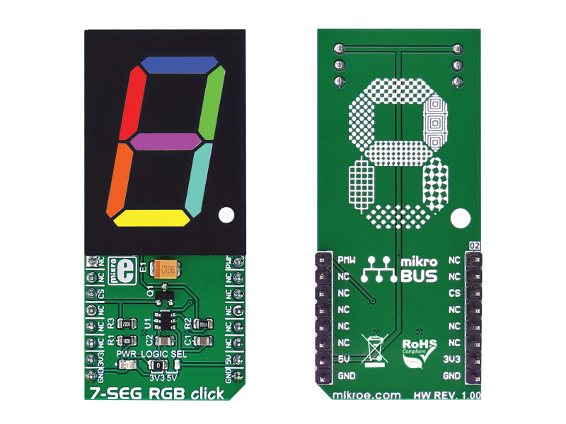
7-SEG RGB click carries a full color single 7 segment digit display. The click is designed to run on either 3.3V or 5V power supply. It communicates with the target microcontroller over the CS, and PWM pin on the mikroBUS line.

No Abuse Reported

Do you want to subscribe in order to receive notifications regarding "7-SEG RGB click" changes.

Do you want to unsubscribe in order to stop receiving notifications regarding "7-SEG RGB click" changes.

Do you want to report abuse regarding "7-SEG RGB click".

  • mikroSDK Library 2.0.0.0
  • Comments (0)

mikroSDK Library Blog

7-SEG RGB

7-SEG RGB

Front and Back view of the 7-SEG RGB board.

View full image

Library Description

The library covers all the necessary functions to control 7-SEG RGB click board.

Key functions:

  • void c7segrgb_gpioDriverInit(T_PS2_P gpioObj) - Function initializes GPIO driver for the desired MIKROBUS1.

Examples description

The application is composed of the three sections :

  • System Initialization - Initializes GPIO, LOG structures.
  • Application Initialization -  Initialization driver enables - GPIO.
  • Application Task - (code snippet) This is an example which demonstrates the use of 7-SEG RGB Click board. This simple example shows all ten numbers in different colors on 7-SEG RGB click.
void applicationTask() 
{
    uint8_t cnt_i;
    uint8_t cnt_j;
    
    for ( cnt_i = 0; cnt_i < 10; cnt_i++ )
    {
        for ( cnt_j = 10; cnt_j > 0; cnt_j-- )
        {
            c7segrgb_setSevenSegment( _CHARACTER_TABLE[ cnt_i ], 4 * cnt_i, 4 * cnt_j, cnt_i * cnt_j );
            Delay_100ms();
        }
    }

    c7segrgb_setSevenSegment( _C7SEGRGB_POINT, 10, 10, 10 );
    Delay_1sec();

    c7segrgb_setSevenSegment( _C7SEGRGB_ZERO, 40, 40, 40 );
    Delay_1sec();

    c7segrgb_setSevenSegment( _C7SEGRGB_ONE, 40, 0, 0 );
    Delay_1sec();

    c7segrgb_setSevenSegment( _C7SEGRGB_TWO, 0, 40, 0 );
    Delay_1sec();

    c7segrgb_setSevenSegment( _C7SEGRGB_THREE, 0, 0, 40 );
    Delay_1sec();

    c7segrgb_setSevenSegment( _C7SEGRGB_FOUR, 40, 0, 40 );
    Delay_1sec();

    c7segrgb_setSevenSegment( _C7SEGRGB_FIVE, 0, 40, 40 );
    Delay_1sec();

    c7segrgb_setSevenSegment( _C7SEGRGB_SIX, 40, 40, 0 );
    Delay_1sec();

    c7segrgb_setSevenSegment( _C7SEGRGB_SEVEN, 20, 30, 40 );
    Delay_1sec();

    c7segrgb_setSevenSegment( _C7SEGRGB_EIGHT, 40, 15, 31 );
    Delay_1sec();

    c7segrgb_setSevenSegment( _C7SEGRGB_NINE, 20, 10, 30 );
    Delay_1sec();

    RGB_CONTROL_BIT = 0;
}        

Additional Functions :

  • void c7segrgb_logicOne() - Generic logic one function.
  • void c7segrgb_logicZero() - Generic logic zero function.
  • void c7segrgb_setColor( uint8_t _green, uint8_t _red, uint8_t _blue ) - Set the color of the  LSB segment of the display function.
  • void c7segrgb_setSevenSegment( uint8_t  _character, uint8_t _greenBrightness, uint8_t _redBrightness, uint8_t _blueBrightness ) - Set whole character and color function.

Other mikroE Libraries used in the example:

  • One_Wire
  • UART​
  • Conversion

Additional notes and informations

Depending on the development board you are using, you may need USB UART clickUSB UART 2 click or RS232 click to connect to your PC, for development systems with no UART to USB interface available on the board. The terminal available in all MikroElektronika compilers, or any other terminal application of your choice, can be used to read the message

ALSO FROM THIS AUTHOR

Hall Switch 3 Click

0

Hall Switch 3 Click is a compact add-on board representing a magnetic field-activated switch. This board features the NMH1000, a Hall-effect magnetic switch from NXP Semiconductor. It is a low-voltage, low-current, and low-output data rate device with a very small size. The switch is most sensitive to a vertical field passing through the top-bottom surfaces, orthogonal to the plane of the Hall Switch 3 Click board™.

[Learn More]

Load Cell 2 click

5

Load cell 2 Click is a weight measurement click which utilizes a load cell element, in order to precisely measure the weight of an object. The Load Cell 2 Click can be used with the strain gauge type of load cells with external differential reference voltage range from 0.1V to 5V.

[Learn More]

3D HALL 5 click

5

3D HALL 5 click is a very accurate, magnetic field sensing Click board, used for sensing the magnetic field directions in all three axes. It relies on an IIS2MDCTR, a low power 3D magnetic sensor, from STMicroelectronics.

[Learn More]