TOP Contributors

  1. MIKROE (2784 codes)
  2. Alcides Ramos (405 codes)
  3. Shawon Shahryiar (307 codes)
  4. jm_palomino (133 codes)
  5. Bugz Bensce (97 codes)
  6. S P (73 codes)
  7. dany (71 codes)
  8. MikroBUS.NET Team (35 codes)
  9. NART SCHINACKOW (34 codes)
  10. Armstrong Subero (27 codes)

Most Downloaded

  1. Timer Calculator (141265 times)
  2. FAT32 Library (74088 times)
  3. Network Ethernet Library (58715 times)
  4. USB Device Library (48822 times)
  5. Network WiFi Library (44525 times)
  6. FT800 Library (44072 times)
  7. GSM click (30803 times)
  8. mikroSDK (29654 times)
  9. PID Library (27355 times)
  10. microSD click (27251 times)
Libstock prefers package manager

Package Manager

We strongly encourage users to use Package manager for sharing their code on Libstock website, because it boosts your efficiency and leaves the end user with no room for error. [more info]

< Back
mikroSDK Library

Buck Boost click

Rating:

6

Author: MIKROE

Last Updated: 2019-01-09

Package Version: 1.0.0.1

mikroSDK Library: 1.0.0.0

Category: Buck-Boost

Downloaded: 8649 times

Not followed.

License: MIT license  

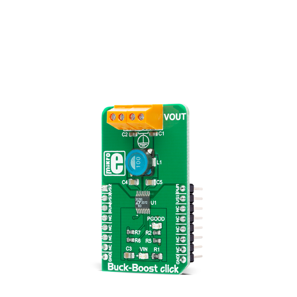
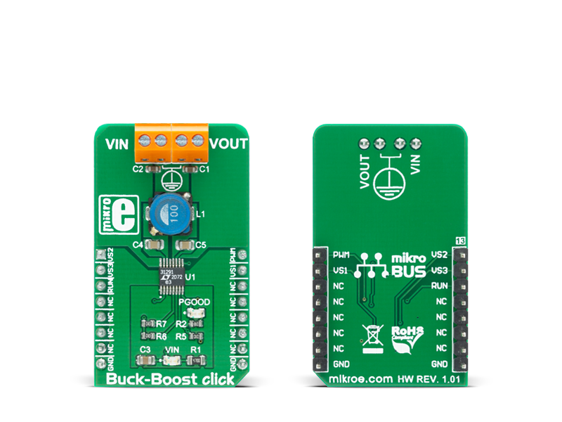
Buck-Boost click features LTC3129-1, a buck-boost DC/DC conversion integrated circuit from Linear Technology®. The click supports wide input voltage range and can output eight discrete regulated voltage levels, selectable by the digital output voltage selection pins, ranging from 2.5V to 15V.

No Abuse Reported

Do you want to subscribe in order to receive notifications regarding "Buck Boost click" changes.

Do you want to unsubscribe in order to stop receiving notifications regarding "Buck Boost click" changes.

Do you want to report abuse regarding "Buck Boost click".

  • mikroSDK Library 2.0.0.0
  • Comments (0)
DOWNLOAD LINK RELATED COMPILER CONTAINS
mikroBasic PRO for ARM
  • lib
  • src
  • exa
  • hlp
  • hex
  • sch
  • pcb
  • doc
mikroBasic PRO for AVR
  • lib
  • src
  • exa
  • hlp
  • hex
  • sch
  • pcb
  • doc
mikroBasic PRO for dsPIC30/33 & PIC24
  • lib
  • src
  • exa
  • hlp
  • hex
  • sch
  • pcb
  • doc
mikroBasic PRO for FT90x
  • lib
  • src
  • exa
  • hlp
  • hex
  • sch
  • pcb
  • doc
mikroBasic PRO for PIC
  • lib
  • src
  • exa
  • hlp
  • hex
  • sch
  • pcb
  • doc
mikroBasic PRO for PIC32
  • lib
  • src
  • exa
  • hlp
  • hex
  • sch
  • pcb
  • doc
mikroC PRO for ARM
  • lib
  • src
  • exa
  • hlp
  • hex
  • sch
  • pcb
  • doc
mikroC PRO for AVR
  • lib
  • src
  • exa
  • hlp
  • hex
  • sch
  • pcb
  • doc
mikroC PRO for dsPIC30/33 & PIC24
  • lib
  • src
  • exa
  • hlp
  • hex
  • sch
  • pcb
  • doc
mikroC PRO for FT90x
  • lib
  • src
  • exa
  • hlp
  • hex
  • sch
  • pcb
  • doc
mikroC PRO for PIC
  • lib
  • src
  • exa
  • hlp
  • hex
  • sch
  • pcb
  • doc
mikroC PRO for PIC32
  • lib
  • src
  • exa
  • hlp
  • hex
  • sch
  • pcb
  • doc
mikroPascal PRO for ARM
  • lib
  • src
  • exa
  • hlp
  • hex
  • sch
  • pcb
  • doc
mikroPascal PRO for AVR
  • lib
  • src
  • exa
  • hlp
  • hex
  • sch
  • pcb
  • doc
mikroPascal PRO for dsPIC30/33 & PIC24
  • lib
  • src
  • exa
  • hlp
  • hex
  • sch
  • pcb
  • doc
mikroPascal PRO for FT90x
  • lib
  • src
  • exa
  • hlp
  • hex
  • sch
  • pcb
  • doc
mikroPascal PRO for PIC
  • lib
  • src
  • exa
  • hlp
  • hex
  • sch
  • pcb
  • doc
mikroPascal PRO for PIC32
  • lib
  • src
  • exa
  • hlp
  • hex
  • sch
  • pcb
  • doc

mikroSDK Library Blog

Buck Boost click

Buck Boost click

Native view of the Buck Boost click board.

View full image
Buck-Boost click

Buck-Boost click

Front and back view of the Buck-Boost click board.

View full image

Library Description

The library covers all the necessary functions to control Buck Boost Click board.
This library contains drivers for set the output value of 
2500 mV, 3300 mV, 4100 mV, 5000 mV, 6900 mV, 8200 mV, 12000 mV and 15000 mV 
to the converter LTC3129-1 on Buck Boost Click.

Key functions:

  • void buckboost_defaultConfig() - Set default configuration function.
  • void buckboost_set2500mV() - Set the output voltage of 2500 mV function.
  • void buckboost_set15000mV() - Set the output voltage of 15000 mV function

Examples description

The application is composed of the three sections :

  • System Initialization - Initializes GPIO and AN, RST, CS, PWM and INT pins as output.
    Application Initialization - Initialization driver enable's - GPIO,
         set default configuration and start write log.
    Application Task - (code snippet) This is a example which demonstrates the use of Buck Boost Click board. Change output voltage from 2500 mV to 15000 mV every 5 seconds. All data logs write on usb uart for aproximetly every 5 sec.
void applicationTask()
{
    mikrobus_logWrite( " Set Output Voltage of 2500 mV ", _LOG_LINE );
    mikrobus_logWrite( "--------------------------------", _LOG_LINE );
    
    buckboost_set2500mV();
    Delay_ms( 5000 );
    
    mikrobus_logWrite( " Set Output Voltage of 3300 mV ", _LOG_LINE );
    mikrobus_logWrite( "--------------------------------", _LOG_LINE );
    
    buckboost_set3300mV();
    Delay_ms( 5000 );

    mikrobus_logWrite( " Set Output Voltage of 4100 mV ", _LOG_LINE );
    mikrobus_logWrite( "--------------------------------", _LOG_LINE );
  
    buckboost_set4100mV();
    Delay_ms( 5000 );

    mikrobus_logWrite( " Set Output Voltage of 5000 mV ", _LOG_LINE ); 
    mikrobus_logWrite( "--------------------------------", _LOG_LINE ); 

    buckboost_set5000mV();
    Delay_ms( 5000 );

    mikrobus_logWrite( " Set Output Voltage of 6900 mV ", _LOG_LINE );
    mikrobus_logWrite( "--------------------------------", _LOG_LINE );
   
    buckboost_set6900mV();
    Delay_ms( 5000 );
    
    mikrobus_logWrite( " Set Output Voltage of 8200 mV ", _LOG_LINE ); 
    mikrobus_logWrite( "--------------------------------", _LOG_LINE );

    buckboost_set8200mV(); 
    Delay_ms( 5000 ); 
    
    mikrobus_logWrite( " Set Output Voltage of 12000 mV ", _LOG_LINE ); 
    mikrobus_logWrite( "--------------------------------", _LOG_LINE ); 

    buckboost_set12000mV(); 
    Delay_ms( 5000 ); 

    mikrobus_logWrite( " Set Output Voltage of 15000 mV ", _LOG_LINE ); 
    mikrobus_logWrite( "--------------------------------", _LOG_LINE ); 

    buckboost_set15000mV();
    Delay_ms( 5000 );
}

Other mikroE Libraries used in the example:

  • GPIO
  • UART

Additional notes and information

Depending on the development board you are using, you may need USB UART clickUSB UART 2 click or RS232 click to connect to your PC, for development systems with no UART to USB interface available on the board. The terminal available in all MikroElektronika compilers, or any other terminal application of your choice, can be used to read the message.

ALSO FROM THIS AUTHOR

IR Grid 3 Click

0

IR Grid 3 Click is a thermal imaging sensor. It has an array of 768 very sensitive, factory calibrated IR elements (pixels), arranged in 32 rows of 24 pixels, each measuring an object temperature up to 300˚C within its local Field of View (FOV). The MLX90640ESF-BAA IR sensor used on this Click board™ has only four pins, and it is mounted inside of the industry standard TO39 package.

[Learn More]

Tester Click

0

Each pin of the mikroBUS™ is routed to a red colored LED, which is protected by 1K resistor.

[Learn More]

ECG GSR Click

0

ECG GSR Click is a complete solution for PPG, ECG and GSR application development, utilizing a specialized IC with a clinical-grade analog front-end (AFE) and electrical front-end. ECG GSR Click uses the AS7030B IC, an ultra-low power, multi-channel bio-sensor, which features a wide range of different options, making it an ideal solution for development of blood oxygen level, heart rate and galvanic skin response monitoring applications, fitness applications, for the ECG bio-authentication, and similar applications related to heart monitoring. ECG GSR Click is also equipped with the 3.5mm electrodes connectors, making it ready to be used out of the box.

[Learn More]