We strongly encourage users to use Package manager for sharing their code on Libstock website, because it boosts your efficiency and leaves the end user with no room for error. [more info]

Rating:
Author: MIKROE
Last Updated: 2018-01-19
Package Version: 1.0.0.0
mikroSDK Library: 1.0.0.0
Category: ADC-DAC
Downloaded: 6919 times
Not followed.
License: MIT license
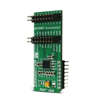
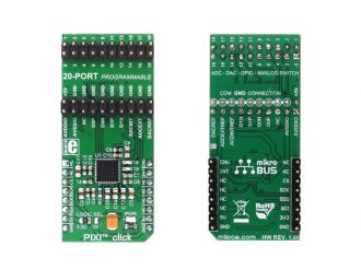
PIXI click is equipped with MAX11300 IC from Maxim Integrated, which features Maxim Integrated's versatile, proprietary PIXI technology - it is the industry's first configurable 20-channel mixed-signal data converter.
Do you want to subscribe in order to receive notifications regarding "PIXI click" changes.
Do you want to unsubscribe in order to stop receiving notifications regarding "PIXI click" changes.
Do you want to report abuse regarding "PIXI click".


Library Description
Key functions
void pixi_writeRegister(uint8_t registerAddress , uint16_t registerData) - Generic function for writing to registers.
uint16_t pixi_readRegister(uint8_t registerAddress)- Generic function for reading from registers.
Examples Description
Simple example of LED blinking off all PIXI™ click pins, ports are configured by writing messages to the appropriate registers via the SPI interface. The low-level communication is taken care of inside the MikroElektronika functions. Registers can be easily accessed with two simple functions:
pixi_writeRegister is the register writing function, which accepts two parameters. The first parameter of the function is the 8bit register that needs to be written, while the second parameter is the 16bit data that is written to the register provided with the first parameter. This function does not return any value
pixi_readRegister is used to read the content of a certain register, which is forwarded as an 8bit parameter. This function returns 16bit data which represents the contents of the register, forwarded as the parameter.
The simple application example periodically sets all the GPIO pins to 5V and then to 0V, with one second delay. More information about the registers and their functions can be found in the MAX11300 datasheet.
void applicationTask()
{
    pixi_writeRegister(0x0D, 0xFFFF); //setting all GPIO to 5V
    pixi_writeRegister(0x0E, 0x000F);
    Delay_ms(1000);
    pixi_writeRegister(0x0D, 0x0000); //setting all GPIO to 0V
    pixi_writeRegister(0x0E, 0x0000);
    Delay_ms(1000);
}
Other mikroE Libraries used in the example:
Additional notes and information
Depending on the development board you are using, you may need USB UART click, USB UART 2 click or RS232 click to connect to your PC, for development systems with no UART to USB interface available on the board. The terminal available in all MikroElektronika compilers, or any other terminal application of your choice, can be used to read the message.