TOP Contributors

  1. MIKROE (2784 codes)
  2. Alcides Ramos (393 codes)
  3. Shawon Shahryiar (307 codes)
  4. jm_palomino (123 codes)
  5. Bugz Bensce (97 codes)
  6. S P (73 codes)
  7. dany (71 codes)
  8. MikroBUS.NET Team (35 codes)
  9. NART SCHINACKOW (34 codes)
  10. Armstrong Subero (27 codes)

Most Downloaded

  1. Timer Calculator (140561 times)
  2. FAT32 Library (73061 times)
  3. Network Ethernet Library (58070 times)
  4. USB Device Library (48249 times)
  5. Network WiFi Library (43842 times)
  6. FT800 Library (43326 times)
  7. GSM click (30367 times)
  8. mikroSDK (29002 times)
  9. PID Library (27120 times)
  10. microSD click (26742 times)
Libstock prefers package manager

Package Manager

We strongly encourage users to use Package manager for sharing their code on Libstock website, because it boosts your efficiency and leaves the end user with no room for error. [more info]

< Back
mikroSDK Library

Servo click

Rating:

5

Author: MIKROE

Last Updated: 2018-08-22

Package Version: 1.0.0.0

mikroSDK Library: 1.0.0.0

Category: Servo

Downloaded: 5454 times

Not followed.

License: MIT license  

Servo click is a 16-channel PWM servo driver with the voltage sensing circuitry. It can be used to simultaneously control 16 servo motors, each with its own programmable PWM signal.

No Abuse Reported

Do you want to subscribe in order to receive notifications regarding "Servo click" changes.

Do you want to unsubscribe in order to stop receiving notifications regarding "Servo click" changes.

Do you want to report abuse regarding "Servo click".
  • mikroSDK Library 2.0.0.0
  • Comments (0)
DOWNLOAD LINK RELATED COMPILER CONTAINS
mikroBasic PRO for ARM
  • lib
  • src
  • exa
  • hlp
  • hex
  • sch
  • pcb
  • doc
mikroBasic PRO for AVR
  • lib
  • src
  • exa
  • hlp
  • hex
  • sch
  • pcb
  • doc
mikroBasic PRO for dsPIC30/33 & PIC24
  • lib
  • src
  • exa
  • hlp
  • hex
  • sch
  • pcb
  • doc
mikroBasic PRO for FT90x
  • lib
  • src
  • exa
  • hlp
  • hex
  • sch
  • pcb
  • doc
mikroBasic PRO for PIC
  • lib
  • src
  • exa
  • hlp
  • hex
  • sch
  • pcb
  • doc
mikroBasic PRO for PIC32
  • lib
  • src
  • exa
  • hlp
  • hex
  • sch
  • pcb
  • doc
mikroC PRO for ARM
  • lib
  • src
  • exa
  • hlp
  • hex
  • sch
  • pcb
  • doc
mikroC PRO for AVR
  • lib
  • src
  • exa
  • hlp
  • hex
  • sch
  • pcb
  • doc
mikroC PRO for dsPIC30/33 & PIC24
  • lib
  • src
  • exa
  • hlp
  • hex
  • sch
  • pcb
  • doc
mikroC PRO for FT90x
  • lib
  • src
  • exa
  • hlp
  • hex
  • sch
  • pcb
  • doc
mikroC PRO for PIC
  • lib
  • src
  • exa
  • hlp
  • hex
  • sch
  • pcb
  • doc
mikroC PRO for PIC32
  • lib
  • src
  • exa
  • hlp
  • hex
  • sch
  • pcb
  • doc
mikroPascal PRO for ARM
  • lib
  • src
  • exa
  • hlp
  • hex
  • sch
  • pcb
  • doc
mikroPascal PRO for AVR
  • lib
  • src
  • exa
  • hlp
  • hex
  • sch
  • pcb
  • doc
mikroPascal PRO for dsPIC30/33 & PIC24
  • lib
  • src
  • exa
  • hlp
  • hex
  • sch
  • pcb
  • doc
mikroPascal PRO for FT90x
  • lib
  • src
  • exa
  • hlp
  • hex
  • sch
  • pcb
  • doc
mikroPascal PRO for PIC
  • lib
  • src
  • exa
  • hlp
  • hex
  • sch
  • pcb
  • doc
mikroPascal PRO for PIC32
  • lib
  • src
  • exa
  • hlp
  • hex
  • sch
  • pcb
  • doc

mikroSDK Library Blog

Servo click

Servo click

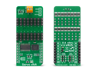
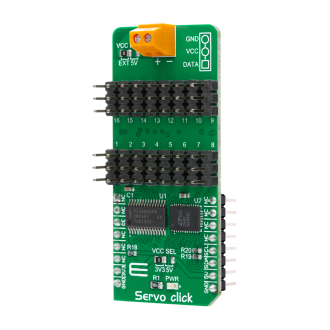
Native view of the Servo click board.

View full image
Servo click

Servo click

Front and back view of the Servo click board.

View full image

Library Description

This library will allow you to control multiple servo motors at once.

Key functions:

  • void servo_init(uint8_t minPosition, uint8_t maxPosition, uint16_t lowResolution, uint16_t highResolution); - Main click board initialization routine.
  • void servo_setMode(uint8_t mode,uint8_t _data); - Set's the operation mode of the click board.
  • servo_sleep(); - The function needs to be set before setting the frequency.
  • void servo_setFREQ(uint16_t freq); - Used for setting the frequency.
  • void servo_setPosition(uint8_t motor, uint8_t position); - Set the position of the selected servo motor.

Example description

The application is composed of three sections:

  • System Initialization - Initializes the I2C module and the CS pin as the output
  • Application Initialization - Initializes the driver and the servo (setting the minimum and maximum servo motors position and resolutions). Default resolution is 1ms. The IC is set to Sleep mode in order to set the frequency, after which the working mode of the servo is set
  • Application Task - (code snippet) - The servo motor is moved across three different positions: 0, 90, 180 - every two seconds. The current consumption is sampled while the servo transitions between these points
void applicationTask()
{
 servo_setPosition(_SERVO_MOTOR_1, 0);
 Delay_ms( 2000 );
 servo_setPosition(_SERVO_MOTOR_1, 90);
 Delay_ms( 1000 );
 servo_setPosition(_SERVO_MOTOR_1, 180);
 Delay_ms( 2000 );
 servo_setPosition(_SERVO_MOTOR_1, 90);

 Current = setvo_getCurrent(_SERVO_POSITIVE_CH0);
 IntToStr(Current , text);
 mikrobus_logWrite( "Current - ", _LOG_TEXT );
 mikrobus_logWrite( text, _LOG_TEXT );
 mikrobus_logWrite( " mA", _LOG_LINE );

 Delay_ms( 1000 );
}


Other MikroElektronika libraries used in the example:

  • I2C Library
  • UART Library
  • Conversions Library
  • C_String Library

ADDITIONAL NOTES AND INFORMATION

Depending on the development board you are using, you may need USB UART clickUSB UART 2 click or RS232 click to connect to your PC, for development systems with no UART to USB interface available on the board. The terminal available in all MikroElektronika compilers, or any other terminal application of your choice, can be used to read the message.

ALSO FROM THIS AUTHOR

CAN Isolator 3 Click

0

CAN Isolator 3 Click is a compact add-on board that provides isolated CAN communication. This board features the MAX14882, an isolated CAN transceiver with an integrated transformer driver from Analog Devices. It is galvanically isolated between the device's CAN-protocol controller side (TDX, RDX) and the physical wires of the CAN network (CANH, CANL) cable-side/bus-side of the transceiver.

[Learn More]

Color 15 Click

0

Color 15 Click is a compact add-on board representing an accurate color sensing solution. This board features the CLS-16D24-44-DF8/TR8, a low power, high sensitivity, color light sensor from Everlight Electronics. This Click boardâ„¢, with an I2C configurable color sensor, senses red, green, blue, white (RGBW), and infrared light and converts them to digital values. The RGBW sensor is designed to reject IR in light sources allowing the device to operate in environments from sunlight to dark rooms. The integrating ADC rejects 50Hz and 60Hz flickers caused by artificial light sources.

[Learn More]

DIGI POT 6 click

5

DIGI POT 6 Click features the MCP41HVX1 family of devices which have dual power rails (analog and digital). The analog power rail allows high voltage on the resistor network terminal pins. The analog voltage range is determined by the V+ and V- voltages.

[Learn More]