TOP Contributors

  1. MIKROE (2639 codes)
  2. Alcides Ramos (347 codes)
  3. Shawon Shahryiar (307 codes)
  4. jm_palomino (112 codes)
  5. Chisanga Mumba (90 codes)
  6. S P (73 codes)
  7. dany (71 codes)
  8. MikroBUS.NET Team (35 codes)
  9. NART SCHINACKOW (34 codes)
  10. Armstrong Subero (27 codes)

Most Downloaded

  1. Timer Calculator (136096 times)
  2. FAT32 Library (69396 times)
  3. Network Ethernet Library (55672 times)
  4. USB Device Library (45940 times)
  5. Network WiFi Library (41608 times)
  6. FT800 Library (40703 times)
  7. GSM click (28763 times)
  8. PID Library (26312 times)
  9. mikroSDK (25995 times)
  10. microSD click (25089 times)
Libstock prefers package manager

Package Manager

We strongly encourage users to use Package manager for sharing their code on Libstock website, because it boosts your efficiency and leaves the end user with no room for error. [more info]

< Back
mikroSDK Library

TouchKey 4 click

Rating:

5

Author: MIKROE

Last Updated: 2018-04-23

Package Version: 1.0.0.0

mikroSDK Library: 1.0.0.0

Category: Capacitive

Downloaded: 4435 times

Not followed.

License: MIT license  

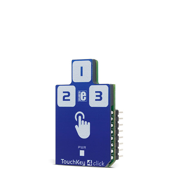
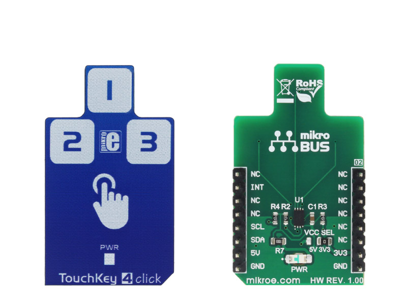
Touch Key 4 click is a capacitive touch sensing Click board, with the advanced touch/proximity sensor IC. Touch Key 4 click has three independently configurable channels and can work in several operating modes, including multiple button pattern detection mode, combo mode, press and hold detection mode, power button mode, and more.

No Abuse Reported

Do you want to subscribe in order to receive notifications regarding "TouchKey 4 click" changes.

Do you want to unsubscribe in order to stop receiving notifications regarding "TouchKey 4 click" changes.

Do you want to report abuse regarding "TouchKey 4 click".

  • mikroSDK Library 2.0.0.0
  • Comments (0)
DOWNLOAD LINK RELATED COMPILER CONTAINS
mikroBasic PRO for ARM
  • lib
  • src
  • exa
  • hlp
  • hex
  • sch
  • pcb
  • doc
mikroBasic PRO for AVR
  • lib
  • src
  • exa
  • hlp
  • hex
  • sch
  • pcb
  • doc
mikroBasic PRO for dsPIC30/33 & PIC24
  • lib
  • src
  • exa
  • hlp
  • hex
  • sch
  • pcb
  • doc
mikroBasic PRO for FT90x
  • lib
  • src
  • exa
  • hlp
  • hex
  • sch
  • pcb
  • doc
mikroBasic PRO for PIC
  • lib
  • src
  • exa
  • hlp
  • hex
  • sch
  • pcb
  • doc
mikroBasic PRO for PIC32
  • lib
  • src
  • exa
  • hlp
  • hex
  • sch
  • pcb
  • doc
mikroC PRO for ARM
  • lib
  • src
  • exa
  • hlp
  • hex
  • sch
  • pcb
  • doc
mikroC PRO for AVR
  • lib
  • src
  • exa
  • hlp
  • hex
  • sch
  • pcb
  • doc
mikroC PRO for dsPIC30/33 & PIC24
  • lib
  • src
  • exa
  • hlp
  • hex
  • sch
  • pcb
  • doc
mikroC PRO for FT90x
  • lib
  • src
  • exa
  • hlp
  • hex
  • sch
  • pcb
  • doc
mikroC PRO for PIC
  • lib
  • src
  • exa
  • hlp
  • hex
  • sch
  • pcb
  • doc
mikroC PRO for PIC32
  • lib
  • src
  • exa
  • hlp
  • hex
  • sch
  • pcb
  • doc
mikroPascal PRO for ARM
  • lib
  • src
  • exa
  • hlp
  • hex
  • sch
  • pcb
  • doc
mikroPascal PRO for AVR
  • lib
  • src
  • exa
  • hlp
  • hex
  • sch
  • pcb
  • doc
mikroPascal PRO for dsPIC30/33 & PIC24
  • lib
  • src
  • exa
  • hlp
  • hex
  • sch
  • pcb
  • doc
mikroPascal PRO for FT90x
  • lib
  • src
  • exa
  • hlp
  • hex
  • sch
  • pcb
  • doc
mikroPascal PRO for PIC
  • lib
  • src
  • exa
  • hlp
  • hex
  • sch
  • pcb
  • doc
mikroPascal PRO for PIC32
  • lib
  • src
  • exa
  • hlp
  • hex
  • sch
  • pcb
  • doc

mikroSDK Library Blog

TouchKey 4 click

TouchKey 4 click

Native view of the TouchKey 4 click board.

View full image
TouchKey 4 click

TouchKey 4 click

Front and back view of the TouchKey 4 click board.

View full image

Library Description

The library initializes and defines I2C bus driver and driver functions which offer a choice to write data in the registers and to read data from the registers. The library also offers a choice to detect touch on enabled sensor inputs in two possible modes, Active and Standby mode.
Every sensor input can be configured to work in both modes at the same time (Combo mode). The sensor inputs can also be configured to detect when touch is released and can generate an interrupt as long as the touch is detected. For more details check the documentation.

Key functions:

void touchkey4_writeReg( const uint8_t register_address, const uint8_t transfer_data ) - The function writes one-byte data in the register.

void touchkey4_readReg( const uint8_t register_address, uint8_t *dataOut, const uint8_t nBytes ) - The function reads data from the register.

void touchkey4_detectTouch( uint8_t *inputSens ) - The function detects touch on the sensor inputs and checks if touch is detected or if touch is released.

void touchkey4_setComboMode( const uint8_t analogGain, const uint8_t enInput1, const uint8_t enInput2, const uint8_t enInput3 ) - Function puts the device in Combo mode (Active and Standby) and enables desired inputs in Active mode, Standby mode or both modes.

Examples Description

  • System Initialization - Initializes peripherals and pins.
  • Application Initialization - IInitializes I2C driver and sets configuration for TouchKey 4 click. TouchKey 4 is configured to works in Combo mode (Active and Standby mode). Input 1 is enabled in Active mode, input 3 is enabled in Standby mode, and input 2 is enabled to works in both modes. In this example, the interrupt will be generated when touch is detected and when touch is released. Also, input 2 will generate an interrupt as long as the touch is detected (press and hold the event), while input 1 and input 3 will generate interrupt only once on one touch detection, after which the touch will be released. Note: Standby mode should be used when fewer sensor inputs are enabled, and when they are programmed to have more sensitivity.
  • Application Task - (code snippet) - Calls function to check touch detection (is interrupt occurred) and shows a message on USB UART if touch is detected or if touch is released on enabled inputs.
void applicationTask()
{
 touchkey4_detectTouch( &sensorResults[0] );
 for (cnt = 0; cnt < 3; cnt++)
 {
 if (sensorResults[ cnt ] == 1)
 {
 if (cnt == 0)
 mikrobus_logWrite( "Input 1 is touched", _LOG_LINE );
 else if (cnt == 1)
 mikrobus_logWrite( "Input 2 is touched", _LOG_LINE );
 else
 mikrobus_logWrite( "Input 3 is touched", _LOG_LINE );
 }
 else if (sensorResults[ cnt ] == 2)
 {
 if (cnt == 0)
 mikrobus_logWrite( "Input 1 is released", _LOG_LINE );
 else if (cnt == 1)
 mikrobus_logWrite( "Input 2 is released", _LOG_LINE );
 else
 mikrobus_logWrite( "Input 3 is released", _LOG_LINE );
 mikrobus_logWrite( "", _LOG_LINE );
 }
 }
}

Other mikroE Libraries used in the example:

  • I2C
  • UART

Additional notes and information

Depending on the development board you are using, you may need USB UART click,  USB UART 2 click or RS232 click to connect to your PC, for development systems with no UART to USB interface available on the board. The terminal available in all MikroElektronika compilers, or any other terminal application of your choice, can be used to read the message.

ALSO FROM THIS AUTHOR

Relay 5 click

0

Relay 5 Click is a compact add-on board with general-purpose relays that any host MCU can control. This board features three J1031C3VDC.15S, a high-current single-pole double-throw (SPDT) signal relays controlled by the PCA9538A, a low-voltage 8-bit I/O port expander from NXP Semiconductors. Highly sensitive, the J1031C3VDC.15S offers a low coil power consumption in a small, lightweight package with PC pin mounting. It comes with a dimension of 12.5x7.5x10 millimeters (LxWxH) and a 1C contact arrangement with a coil voltage of 3VDC, providing a maximum switching voltage of 125VAC/60VDC.

[Learn More]

SPI Isolator 4 click

0

SPI Isolator 4 Click is a compact add-on board that contains a digital isolator optimized for a serial peripheral interface. This board features the ADuM341E, a quad-channel 5kVRMS digital isolator from Analog Devices. This board features the ADuM341E, a quad-channel 5kVRMS digital isolator from Analog Devices. This isolation component provides outstanding performance by combining high speed, complementary metal-oxide-semiconductor (CMOS), and monolithic air core transformer technology. Its data channels are independent and available in various configurations with a withstand voltage rating of 5kVrms, and operate with the external supply voltage ranging from 2.25V to 5.5V, providing compatibility with lower voltage systems enabling voltage translation functionality across the isolation barrier.

[Learn More]

BATT-MAN 3 click

0

BATT-MAN 3 Click is a compact add-on board representing an advanced battery management solution. This board features the ADP5350, a power management IC with inductive boost LED, and three LDO regulators from Analog Devices. This I2C programmable board supports USB optimized for USB voltage input. It combines one high-performance buck regulator for single Li-Ion/Li-Ion polymer battery charging, a fuel gauge, a highly programmable boost regulator for LED backlight illumination, and three 150mA LDO regulators.

[Learn More]