TOP Contributors

  1. MIKROE (2784 codes)
  2. Alcides Ramos (405 codes)
  3. Shawon Shahryiar (307 codes)
  4. jm_palomino (133 codes)
  5. Bugz Bensce (97 codes)
  6. S P (73 codes)
  7. dany (71 codes)
  8. MikroBUS.NET Team (35 codes)
  9. NART SCHINACKOW (34 codes)
  10. Armstrong Subero (27 codes)

Most Downloaded

  1. Timer Calculator (141158 times)
  2. FAT32 Library (73970 times)
  3. Network Ethernet Library (58587 times)
  4. USB Device Library (48754 times)
  5. Network WiFi Library (44440 times)
  6. FT800 Library (44024 times)
  7. GSM click (30783 times)
  8. mikroSDK (29505 times)
  9. PID Library (27324 times)
  10. microSD click (27187 times)
Libstock prefers package manager

Package Manager

We strongly encourage users to use Package manager for sharing their code on Libstock website, because it boosts your efficiency and leaves the end user with no room for error. [more info]

< Back
mikroSDK Library

Clock Gen 2 click

Rating:

5

Author: MIKROE

Last Updated: 2018-07-04

Package Version: 1.0.0.0

mikroSDK Library: 1.0.0.0

Category: Clock generator

Downloaded: 5628 times

Not followed.

License: MIT license  

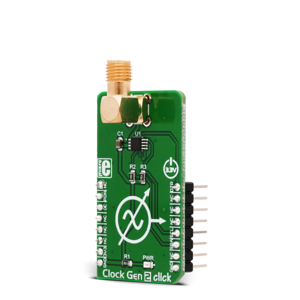
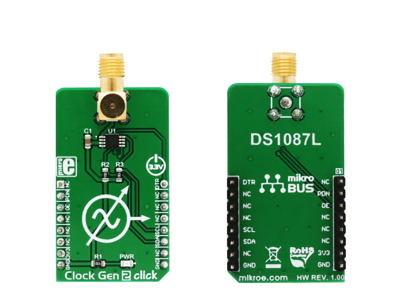
Clock Gen 2 click is an accurate square wave generator that can generate a clock signal in the range from 260kHz to 66.6MHz.

No Abuse Reported

Do you want to subscribe in order to receive notifications regarding "Clock Gen 2 click" changes.

Do you want to unsubscribe in order to stop receiving notifications regarding "Clock Gen 2 click" changes.

Do you want to report abuse regarding "Clock Gen 2 click".

  • mikroSDK Library 2.0.0.0
  • Comments (0)
DOWNLOAD LINK RELATED COMPILER CONTAINS
mikroBasic PRO for ARM
  • lib
  • src
  • exa
  • hlp
  • hex
  • sch
  • pcb
  • doc
mikroBasic PRO for AVR
  • lib
  • src
  • exa
  • hlp
  • hex
  • sch
  • pcb
  • doc
mikroBasic PRO for dsPIC30/33 & PIC24
  • lib
  • src
  • exa
  • hlp
  • hex
  • sch
  • pcb
  • doc
mikroBasic PRO for FT90x
  • lib
  • src
  • exa
  • hlp
  • hex
  • sch
  • pcb
  • doc
mikroBasic PRO for PIC
  • lib
  • src
  • exa
  • hlp
  • hex
  • sch
  • pcb
  • doc
mikroBasic PRO for PIC32
  • lib
  • src
  • exa
  • hlp
  • hex
  • sch
  • pcb
  • doc
mikroC PRO for ARM
  • lib
  • src
  • exa
  • hlp
  • hex
  • sch
  • pcb
  • doc
mikroC PRO for AVR
  • lib
  • src
  • exa
  • hlp
  • hex
  • sch
  • pcb
  • doc
mikroC PRO for dsPIC30/33 & PIC24
  • lib
  • src
  • exa
  • hlp
  • hex
  • sch
  • pcb
  • doc
mikroC PRO for FT90x
  • lib
  • src
  • exa
  • hlp
  • hex
  • sch
  • pcb
  • doc
mikroC PRO for PIC
  • lib
  • src
  • exa
  • hlp
  • hex
  • sch
  • pcb
  • doc
mikroC PRO for PIC32
  • lib
  • src
  • exa
  • hlp
  • hex
  • sch
  • pcb
  • doc
mikroPascal PRO for ARM
  • lib
  • src
  • exa
  • hlp
  • hex
  • sch
  • pcb
  • doc
mikroPascal PRO for AVR
  • lib
  • src
  • exa
  • hlp
  • hex
  • sch
  • pcb
  • doc
mikroPascal PRO for dsPIC30/33 & PIC24
  • lib
  • src
  • exa
  • hlp
  • hex
  • sch
  • pcb
  • doc
mikroPascal PRO for FT90x
  • lib
  • src
  • exa
  • hlp
  • hex
  • sch
  • pcb
  • doc
mikroPascal PRO for PIC
  • lib
  • src
  • exa
  • hlp
  • hex
  • sch
  • pcb
  • doc
mikroPascal PRO for PIC32
  • lib
  • src
  • exa
  • hlp
  • hex
  • sch
  • pcb
  • doc

mikroSDK Library Blog

 Clock Gen 2 click

Clock Gen 2 click

Native view of the Clock Gen 2 click board.

View full image
 Clock Gen 2 click

Clock Gen 2 click

Front and back view of the Clock Gen 2 click board.

View full image

Library Description

Library provides basic functions for setting different clock output frequencies.

Key functions :

void clockgen2_setPrescaler(uint8_t VAL); - Function for setting the clock prescaler.

void clockgen2_changeAddress(uint8_t _newAddr); - Function for changing the default address.

void clockgen2_outputEnable(uint8_t state); - Function for enabling the clock output.


Examples Description

The application is composed of three sections :


  • System Initialization - Initialize GPIO and I2C structures.
  • Application Initialization - Driver initialization.
  • Application Task - Changes the prescaler and enables/disables the clock output.


void applicationTask()
{
char i;

for( i = 5; i< 8; i++ )
{
clockgen2_setPrescaler(i);
clockgen2_outputEnable(1);
Delay_ms(2000);clockgen2_outputEnable(0);
Delay_ms(2000); 
}
}

Other mikroE Libraries used in the example:

  • I2C Library


Additional notes and information

Depending on the development board you are using, you may need USB UART clickUSB UART 2 click or RS232 click to connect to your PC, for development systems with no UART to USB interface available on the board. The terminal available in all MikroElektronika compilers, or any other terminal application of your choice, can be used to read the message.

ALSO FROM THIS AUTHOR

Grid-EYE 2 Click

0

Grid-EYE 2 Click is a compact add-on board designed for thermal imaging and motion detection applications. This board features the AMG883543, an infrared array sensor from Panasonic with a 90° viewing angle and an 8x8 pixel matrix that measures temperatures from 0°C to 80°C with a resolution of 0.25°C. The sensor can detect objects up to 5 meters away and outputs temperature data via a digital interface. The board also supports the Click Snap feature, allowing the main sensor area to be detached for flexible positioning.

[Learn More]

Solar Energy 2 Click

0

Solar Energy 2 Click is a compact add-on board that can recharge a battery by harvesting the solar power of the Sun or by other means. This board features the EM8500, a power management controller with an energy harvesting interface from EM Microelectronic. The controller is specifically designed for efficient harvesting over various DC sources such as photovoltaic (solar) or thermal electric generators (TEG). It can recharge the connected LiPo battery or supercapacitor (or even a conventional capacitor). In addition, the EM8500 can use the same battery as a power source for powering the connected system.

[Learn More]

WiFi ESP click

2

WiFi ESP click carries the ESP-WROOM-02 module that integrates ESP8266EX. The click is designed to run on a 3.3V power supply. It communicates with the target microcontroller over UART interface and the following pins on the mikroBUS line: RST, CS.

[Learn More]