TOP Contributors

  1. MIKROE (2762 codes)
  2. Alcides Ramos (374 codes)
  3. Shawon Shahryiar (307 codes)
  4. jm_palomino (118 codes)
  5. Bugz Bensce (90 codes)
  6. S P (73 codes)
  7. dany (71 codes)
  8. MikroBUS.NET Team (35 codes)
  9. NART SCHINACKOW (34 codes)
  10. Armstrong Subero (27 codes)

Most Downloaded

  1. Timer Calculator (139248 times)
  2. FAT32 Library (71743 times)
  3. Network Ethernet Library (57115 times)
  4. USB Device Library (47428 times)
  5. Network WiFi Library (43082 times)
  6. FT800 Library (42403 times)
  7. GSM click (29835 times)
  8. mikroSDK (28073 times)
  9. PID Library (26885 times)
  10. microSD click (26198 times)
Libstock prefers package manager

Package Manager

We strongly encourage users to use Package manager for sharing their code on Libstock website, because it boosts your efficiency and leaves the end user with no room for error. [more info]

< Back
mikroSDK Library

Color 5 click

Rating:

5

Author: MIKROE

Last Updated: 2018-07-27

Package Version: 1.0.0.0

mikroSDK Library: 1.0.0.0

Category: Optical

Downloaded: 4054 times

Not followed.

License: MIT license  

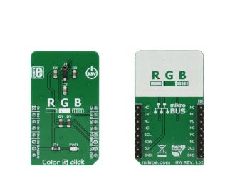
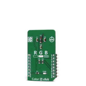
Color 5 click is a color sensing Click board, which utilizes the P12347-01CT, integrated color sensing device, which can sense red (R), green (G), and blue (B) component of the light, providing measurement via I2C interface.

No Abuse Reported

Do you want to subscribe in order to receive notifications regarding "Color 5 click" changes.

Do you want to unsubscribe in order to stop receiving notifications regarding "Color 5 click" changes.

Do you want to report abuse regarding "Color 5 click".
  • Information
  • Comments (0)
DOWNLOAD LINK RELATED COMPILER CONTAINS
mikroBasic PRO for ARM
  • lib
  • src
  • exa
  • hlp
  • hex
  • sch
  • pcb
  • doc
mikroBasic PRO for AVR
  • lib
  • src
  • exa
  • hlp
  • hex
  • sch
  • pcb
  • doc
mikroBasic PRO for dsPIC30/33 & PIC24
  • lib
  • src
  • exa
  • hlp
  • hex
  • sch
  • pcb
  • doc
mikroBasic PRO for FT90x
  • lib
  • src
  • exa
  • hlp
  • hex
  • sch
  • pcb
  • doc
mikroBasic PRO for PIC
  • lib
  • src
  • exa
  • hlp
  • hex
  • sch
  • pcb
  • doc
mikroBasic PRO for PIC32
  • lib
  • src
  • exa
  • hlp
  • hex
  • sch
  • pcb
  • doc
mikroC PRO for ARM
  • lib
  • src
  • exa
  • hlp
  • hex
  • sch
  • pcb
  • doc
mikroC PRO for AVR
  • lib
  • src
  • exa
  • hlp
  • hex
  • sch
  • pcb
  • doc
mikroC PRO for dsPIC30/33 & PIC24
  • lib
  • src
  • exa
  • hlp
  • hex
  • sch
  • pcb
  • doc
mikroC PRO for FT90x
  • lib
  • src
  • exa
  • hlp
  • hex
  • sch
  • pcb
  • doc
mikroC PRO for PIC
  • lib
  • src
  • exa
  • hlp
  • hex
  • sch
  • pcb
  • doc
mikroC PRO for PIC32
  • lib
  • src
  • exa
  • hlp
  • hex
  • sch
  • pcb
  • doc
mikroPascal PRO for ARM
  • lib
  • src
  • exa
  • hlp
  • hex
  • sch
  • pcb
  • doc
mikroPascal PRO for AVR
  • lib
  • src
  • exa
  • hlp
  • hex
  • sch
  • pcb
  • doc
mikroPascal PRO for dsPIC30/33 & PIC24
  • lib
  • src
  • exa
  • hlp
  • hex
  • sch
  • pcb
  • doc
mikroPascal PRO for FT90x
  • lib
  • src
  • exa
  • hlp
  • hex
  • sch
  • pcb
  • doc
mikroPascal PRO for PIC
  • lib
  • src
  • exa
  • hlp
  • hex
  • sch
  • pcb
  • doc
mikroPascal PRO for PIC32
  • lib
  • src
  • exa
  • hlp
  • hex
  • sch
  • pcb
  • doc

mikroSDK Library Blog

Color 5 click

Color 5 click

Native view of the Color 5 click board.

View full image
Color 5 click

Color 5 click

Front and back view of the Color 5 click board.

View full image

Library Description

The library initializes and defines the I2C bus driver and drivers that offer a choice for writing data in the register. The library includes a function to read the color through a red, green, and blue filter and IR data. The user can set the color of the LEDs. The sensor has a proximity mode with which it can detect the object in front of the sensor. The user has a function for reading light through one filter as well as reading the light through all the filters.

Key functions:

  • void color5_setConfiguration(uint8_t reg, uint8_t _data) - Functions for configuration sensor
  • void color5_setLedDriver(uint8_t red, uint8_t green, uint8_t blue) - Functions for setting led color
  • uint16_t color5_readData(uint8_t reg) - Functions for reading data from register
  • uint8_t color5_getInterrupt() - Functions for proximity detect

Example description

The application is composed of three sections :

  • System Initialization - Initializes I2C module
  • Application Initialization - Initializes driver init and configuration proximity and led driver
  • Application Task - (code snippet) - Reads the color values through a red, blue, green filter and IR data. Checking that the proximity sensor detects the object.
void applicationTask()
{
 // Color init
 color5_setConfiguration(_COLOR5_REG_RGB_SENSOR_CTRL,
                         _COLOR5_CFG_SENSOR_RESET 
                       | _COLOR5_CFG_MANUAL_SETTINGS_MODE );
 color5_setConfiguration(_COLOR5_REG_RGB_SENSOR_CTRL, 
                         _COLOR5_CFG_LOW_GAIN 
                      | _COLOR5_CFG_MANUAL_SETTINGS_MODE );

 RED_Data = color5_readData( _COLOR5_REG_OUT_DATA_RED_MSB );
 IntToStr( RED_Data, dataTxt );
 mikrobus_logWrite( "RED data : ", _LOG_TEXT );
 mikrobus_logWrite( dataTxt, _LOG_TEXT );
 mikrobus_logWrite( " nm", _LOG_LINE );

 GREEN_Data = color5_readData( _COLOR5_REG_OUT_DATA_GREEN_MSB );
 IntToStr( GREEN_Data, dataTxt );
 mikrobus_logWrite( "GREEN data : ", _LOG_TEXT );
 mikrobus_logWrite( dataTxt, _LOG_TEXT );
 mikrobus_logWrite( " nm", _LOG_LINE );

 BLUE_Data = color5_readData( _COLOR5_REG_OUT_DATA_BLUE_MSB );
 IntToStr( BLUE_Data, dataTxt );
 mikrobus_logWrite( "BLUE data : ", _LOG_TEXT );
 mikrobus_logWrite( dataTxt, _LOG_TEXT );
 mikrobus_logWrite( " nm", _LOG_LINE );

 IR_Data = color5_readData( _COLOR5_REG_OUT_DATA_IR_MSB );
 IntToStr( IR_Data, dataTxt );
 mikrobus_logWrite( "IR data : ", _LOG_TEXT );
 mikrobus_logWrite( dataTxt, _LOG_TEXT );
 mikrobus_logWrite( " nm", _LOG_LINE );

 mikrobus_logWrite("---------------rn", _LOG_LINE);


 if (color5_getInterrupt() == 1)
 {
 mikrobus_logWrite("Proximity detect", _LOG_LINE);
 }
 Delay_ms( 500 );
}

Other mikroE Libraries used in the example:

  • Conversions
  • I2C
  • UART

Additional notes and information

Depending on the development board you are using, you may need USB UART clickUSB UART 2 click or RS232 click to connect to your PC, for development systems with no UART to USB interface available on the board. The terminal available in all MikroElektronika compilers, or any other terminal application of your choice, can be used to read the message.

ALSO FROM THIS AUTHOR

Step Down 3 Click

0

Step Down 3 Click is a compact add-on board that steps down the voltage from its input to its output. This board features the ST1PS03, a nano-quiescent miniaturized synchronous step-down converter with a load switch from STMicroelectronics. The ST1PS03 can provide up to 400mA output current with an input voltage ranging from 1.8V to 5.5V, specifically designed for applications where high efficiency is crucial. It also embeds a controlled switch accessible from auxiliary channel input to supply a subsystem, output voltage from 1.6V to 3.3V set using three digital control inputs, and a Power Good signal to indicate stabilized output voltages.

[Learn More]

DC Motor 19 Click

0

DC Motor 19 Click is a compact add-on board that contains a brushed DC motor driver. This board features the TC78H653FTG, a dual H-bridge driver for one or two DC brushed motors or one stepping motor, which incorporates DMOS with low ON resistance in output transistors from Toshiba Semiconductor.

[Learn More]

Flash 10 Click

0

Flash 10 Click is a compact add-on board representing a highly reliable memory solution. This board features the AT25FF321A, an SPI configurable 32Mbit (2Mx16) serial Flash memory solution from Dialog Semiconductor. The AT25FF321A is an ideal solution for systems in which program code is shadowed from Flash memory into embedded or external RAM (code shadow) for execution and where small amounts of data are stored and updated locally in the Flash memory. It has a flexible and optimized erase architecture for code and data storage applications, non-volatile protection, and four specialized 128-byte OTP security registers to store a unique device ID and locked key storage. This memory can withstand many write cycles (minimum 100k) and has a data retention period greater than 20 years.

[Learn More]