TOP Contributors

  1. MIKROE (2784 codes)
  2. Alcides Ramos (405 codes)
  3. Shawon Shahryiar (307 codes)
  4. jm_palomino (133 codes)
  5. Bugz Bensce (97 codes)
  6. S P (73 codes)
  7. dany (71 codes)
  8. MikroBUS.NET Team (35 codes)
  9. NART SCHINACKOW (34 codes)
  10. Armstrong Subero (27 codes)

Most Downloaded

  1. Timer Calculator (142088 times)
  2. FAT32 Library (75339 times)
  3. Network Ethernet Library (59511 times)
  4. USB Device Library (49528 times)
  5. Network WiFi Library (45313 times)
  6. FT800 Library (44944 times)
  7. GSM click (31453 times)
  8. mikroSDK (30477 times)
  9. microSD click (27806 times)
  10. PID Library (27626 times)
Libstock prefers package manager

Package Manager

We strongly encourage users to use Package manager for sharing their code on Libstock website, because it boosts your efficiency and leaves the end user with no room for error. [more info]

< Back
mikroSDK Library

Accel 6 click

Rating:

5

Author: MIKROE

Last Updated: 2018-06-29

Package Version: 1.0.0.0

mikroSDK Library: 1.0.0.0

Category: Motion

Downloaded: 5624 times

Not followed.

License: MIT license  

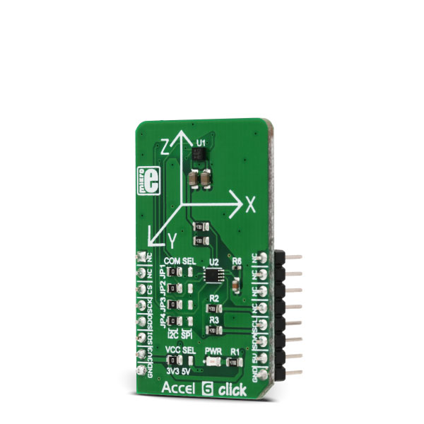
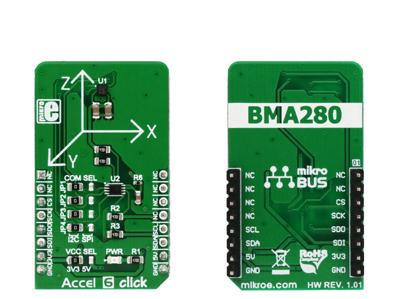
Accel 6 click is a three-axis acceleration sensor with many features. It uses the BMA280, a 14bit triaxial acceleration sensor with intelligent on-chip motion triggered interrupt controller, from Bosch Sensortec.

No Abuse Reported

Do you want to subscribe in order to receive notifications regarding "Accel 6 click" changes.

Do you want to unsubscribe in order to stop receiving notifications regarding "Accel 6 click" changes.

Do you want to report abuse regarding "Accel 6 click".

  • mikroSDK Library 2.0.0.0
  • Comments (0)
DOWNLOAD LINK RELATED COMPILER CONTAINS
mikroBasic PRO for ARM
  • lib
  • src
  • exa
  • hlp
  • hex
  • sch
  • pcb
  • doc
mikroBasic PRO for AVR
  • lib
  • src
  • exa
  • hlp
  • hex
  • sch
  • pcb
  • doc
mikroBasic PRO for dsPIC30/33 & PIC24
  • lib
  • src
  • exa
  • hlp
  • hex
  • sch
  • pcb
  • doc
mikroBasic PRO for FT90x
  • lib
  • src
  • exa
  • hlp
  • hex
  • sch
  • pcb
  • doc
mikroBasic PRO for PIC
  • lib
  • src
  • exa
  • hlp
  • hex
  • sch
  • pcb
  • doc
mikroBasic PRO for PIC32
  • lib
  • src
  • exa
  • hlp
  • hex
  • sch
  • pcb
  • doc
mikroC PRO for ARM
  • lib
  • src
  • exa
  • hlp
  • hex
  • sch
  • pcb
  • doc
mikroC PRO for AVR
  • lib
  • src
  • exa
  • hlp
  • hex
  • sch
  • pcb
  • doc
mikroC PRO for dsPIC30/33 & PIC24
  • lib
  • src
  • exa
  • hlp
  • hex
  • sch
  • pcb
  • doc
mikroC PRO for FT90x
  • lib
  • src
  • exa
  • hlp
  • hex
  • sch
  • pcb
  • doc
mikroC PRO for PIC
  • lib
  • src
  • exa
  • hlp
  • hex
  • sch
  • pcb
  • doc
mikroC PRO for PIC32
  • lib
  • src
  • exa
  • hlp
  • hex
  • sch
  • pcb
  • doc
mikroPascal PRO for ARM
  • lib
  • src
  • exa
  • hlp
  • hex
  • sch
  • pcb
  • doc
mikroPascal PRO for AVR
  • lib
  • src
  • exa
  • hlp
  • hex
  • sch
  • pcb
  • doc
mikroPascal PRO for dsPIC30/33 & PIC24
  • lib
  • src
  • exa
  • hlp
  • hex
  • sch
  • pcb
  • doc
mikroPascal PRO for FT90x
  • lib
  • src
  • exa
  • hlp
  • hex
  • sch
  • pcb
  • doc
mikroPascal PRO for PIC
  • lib
  • src
  • exa
  • hlp
  • hex
  • sch
  • pcb
  • doc
mikroPascal PRO for PIC32
  • lib
  • src
  • exa
  • hlp
  • hex
  • sch
  • pcb
  • doc

mikroSDK Library Blog

Accel 6 click

Accel 6 click

Native view of the Accel 6 click board.

View full image
Accel 6 click

Accel 6 click

Front and back view of the Accel 6 click board.

View full image

Library Description

The library initializes and defines the I2C bus driver and drivers that offer a choice for writing data in the register. The library includes the function for reading the X/Y/Z axis data, orient chip, detect tap and slope on the chip and function for reading the temperature data. The user also has the function for initializes chip, set offset and software reset.

Key functions:

  • float accel6_getAxis(uint8_t axis) - Functions for reading the axis data.
  • void accel6_getOrient(uint8_t *z_orient, uint8_t *xy_orient) - Functions for reading the orient.
  • uint8_t accel6_getTapStatus() - Functions for detect tap on the x/y/z axis.

Example description

The application is composed of three sections:

  • System Initialization -  Initializes I2C module.
  • Application Initialization - Initializes Driver init and settings accelerometer data range, bandwidth, mode and sleep timer which are necessary for the init chip.
  • Application Task - (code snippet) - Reads the Accel X / Y / Z axis data in mg, 
    Temperature data in C, detects the orientation of the X,Y, and Z axis
    and checking on which axis the tap is detected.
    All data logs on USB UART for every 500 ms.
void applicationTask()
{
 mikrobus_logWrite(" X axis : ", _LOG_TEXT);
 fAxis = accel6_getAxis(_ACCEL6_AXIS_X);
 FloatToStr(fAxis, demoText);
 mikrobus_logWrite(demoText, _LOG_TEXT);
 mikrobus_logWrite(" mg ", _LOG_LINE);

 mikrobus_logWrite(" Y axis : ", _LOG_TEXT);
 fAxis = accel6_getAxis(_ACCEL6_AXIS_Y);
 FloatToStr(fAxis, demoText);
 mikrobus_logWrite(demoText, _LOG_TEXT);
 mikrobus_logWrite(" mg ", _LOG_LINE);

 mikrobus_logWrite(" Z axis : ", _LOG_TEXT);
 fAxis = accel6_getAxis(_ACCEL6_AXIS_Y);
 FloatToStr(fAxis, demoText);
 mikrobus_logWrite(demoText, _LOG_TEXT);
 mikrobus_logWrite(" mg ", _LOG_LINE);

 mikrobus_logWrite(" Temperature : ", _LOG_TEXT);
 Temp = accel6_getTemperature();
 FloatToStr(Temp, demoText);
 mikrobus_logWrite(demoText, _LOG_TEXT);
 mikrobus_logWrite(" C ", _LOG_LINE);

 accel6_getOrient(&z_orient[0], &xy_orient[0]);

 switch(z_orient[0])
 {
 case 1:
 {
 mikrobus_logWrite(" Z orient : UPWARD looking ", _LOG_LINE);
 break;
 }
 case 2:
 {
 mikrobus_logWrite(" Z orient : DOWNWARD looking ", _LOG_LINE);
 break;
 }
 default:
 {
 break;
 }
 }

 switch(xy_orient[0])
 {
 case 1:
 {
 mikrobus_logWrite(" XY orient : UPSIDE DOWN ", _LOG_LINE);
 break;
 }
 case 2:
 {
 mikrobus_logWrite(" XY orient : LANDSCAPE LEFT ", _LOG_LINE);
 break;
 }
 case 3:
 {
 mikrobus_logWrite(" XY orient : LANDSCAPE RIGHT ", _LOG_LINE);
 break;
 }
 case 4:
 {
 mikrobus_logWrite(" XY orient : UPRIGHT ", _LOG_LINE);
 break;
 }
 default:
 {
 break;
 }
 }

 tap_detect = accel6_getTapStatus();
 switch( tap_detect )
 {
 case 1:
 {
 mikrobus_logWrite(" Tap status : X negative ", _LOG_LINE);
 break;
 }
 case 2:
 {
 mikrobus_logWrite(" Tap status : Y negative ", _LOG_LINE);
 break;
 }
 case 3:
 {
 mikrobus_logWrite(" Tap status : Z negative ", _LOG_LINE);
 break;
 }
 case 4:
 {
 mikrobus_logWrite(" Tap status : X positive ", _LOG_LINE);
 break;
 }
 case 5:
 {
 mikrobus_logWrite(" Tap status : Y positive ", _LOG_LINE);
 break;
 }
 case 6:
 {
 mikrobus_logWrite(" Tap status : Z positive ", _LOG_LINE);
 break;
 }
 default:
 {
 break;
 }
 }

 mikrobus_logWrite(" ", _LOG_LINE);
 Delay_ms( 500 );
}


Other MikroElektronika libraries used in the example:

  • I2C
  • UART
  • Conversions

Additional notes and information

Depending on the development board you are using, you may need USB UART clickUSB UART 2 click or RS232 click to connect to your PC, for development systems with no UART to USB interface available on the board. The terminal available in all MikroElektronika compilers, or any other terminal application of your choice, can be used to read the message.

ALSO FROM THIS AUTHOR

6DOF IMU 11 click

5

The 6DOF IMU 11 click is a Click board based on the KMX63, a 6 Degrees-of-Freedom inertial sensor system on a single, silicon chip, which is designed to strike a balance between current consumption and noise performance with excellent bias stability over temperature.

[Learn More]

Thunder click

0

Example demonstrates usage of AS3935 Lighting sensor. It will detect approaching thunderstorm and display on TFT estimated distance and energy. Also user will be warned with buzzer beep.

[Learn More]

LED Driver 16 Click

0

LED Driver 16 Click is a compact add-on board that simplifies the control of multiple LEDs. This board features the PCA9745B, an SPI-configurable sixteen-channel constant current LED driver from NXP Semiconductors. Each LED output has an 8-bit resolution (256 steps) fixed-frequency individual PWM controller that operates at 31.25kHz with an adjustable duty cycle from 0 to 100% to allow the LED to be set to a specific brightness value. Powered through a selected mikroBUS™ power rail, either 3.3V or 5V, it provides a maximum output current of 57mA per channel and multiple built-in protection functions that protect the circuit during abnormalities.

[Learn More]