TOP Contributors

  1. MIKROE (2784 codes)
  2. Alcides Ramos (402 codes)
  3. Shawon Shahryiar (307 codes)
  4. jm_palomino (129 codes)
  5. Bugz Bensce (97 codes)
  6. S P (73 codes)
  7. dany (71 codes)
  8. MikroBUS.NET Team (35 codes)
  9. NART SCHINACKOW (34 codes)
  10. Armstrong Subero (27 codes)

Most Downloaded

  1. Timer Calculator (140768 times)
  2. FAT32 Library (73356 times)
  3. Network Ethernet Library (58200 times)
  4. USB Device Library (48385 times)
  5. Network WiFi Library (43977 times)
  6. FT800 Library (43538 times)
  7. GSM click (30467 times)
  8. mikroSDK (29170 times)
  9. PID Library (27169 times)
  10. microSD click (26848 times)
Libstock prefers package manager

Package Manager

We strongly encourage users to use Package manager for sharing their code on Libstock website, because it boosts your efficiency and leaves the end user with no room for error. [more info]

< Back
mikroSDK Library

Boost-INV click

Rating:

5

Author: MIKROE

Last Updated: 2018-08-15

Package Version: 1.0.0.0

mikroSDK Library: 1.0.0.0

Category: Boost

Downloaded: 4494 times

Not followed.

License: MIT license  

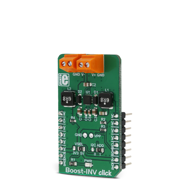
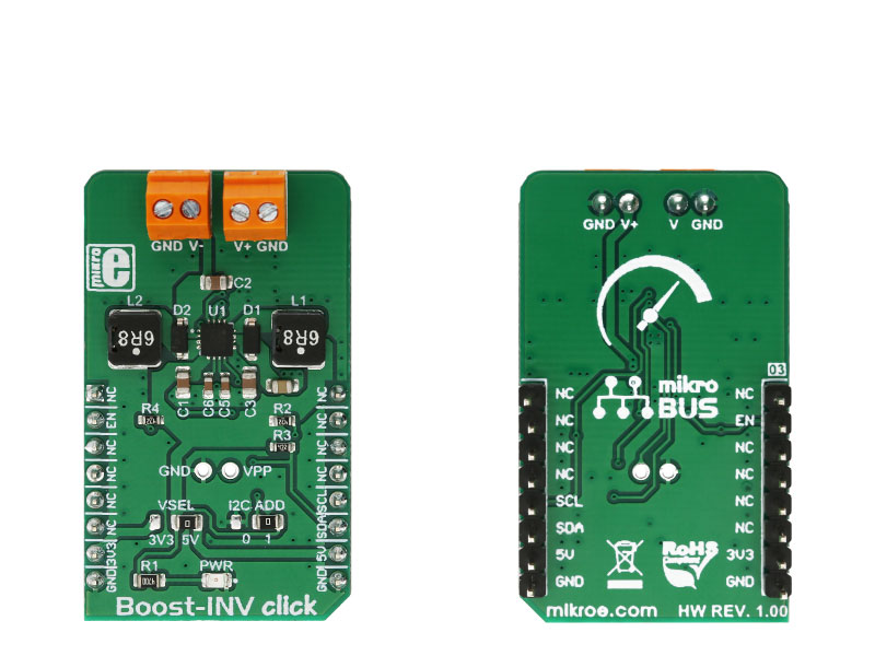
Boost-INV click is a very useful DC/DC voltage converter device, as can output both positive and negative voltage, boosted up to 12.78V and -13.95, from a single fixed voltage input.

No Abuse Reported

Do you want to subscribe in order to receive notifications regarding "Boost-INV click" changes.

Do you want to unsubscribe in order to stop receiving notifications regarding "Boost-INV click" changes.

Do you want to report abuse regarding "Boost-INV click".

  • mikroSDK Library 2.0.0.0
  • Comments (0)
DOWNLOAD LINK RELATED COMPILER CONTAINS
mikroBasic PRO for ARM
  • lib
  • src
  • exa
  • hlp
  • hex
  • sch
  • pcb
  • doc
mikroBasic PRO for AVR
  • lib
  • src
  • exa
  • hlp
  • hex
  • sch
  • pcb
  • doc
mikroBasic PRO for dsPIC30/33 & PIC24
  • lib
  • src
  • exa
  • hlp
  • hex
  • sch
  • pcb
  • doc
mikroBasic PRO for FT90x
  • lib
  • src
  • exa
  • hlp
  • hex
  • sch
  • pcb
  • doc
mikroBasic PRO for PIC
  • lib
  • src
  • exa
  • hlp
  • hex
  • sch
  • pcb
  • doc
mikroBasic PRO for PIC32
  • lib
  • src
  • exa
  • hlp
  • hex
  • sch
  • pcb
  • doc
mikroC PRO for ARM
  • lib
  • src
  • exa
  • hlp
  • hex
  • sch
  • pcb
  • doc
mikroC PRO for AVR
  • lib
  • src
  • exa
  • hlp
  • hex
  • sch
  • pcb
  • doc
mikroC PRO for dsPIC30/33 & PIC24
  • lib
  • src
  • exa
  • hlp
  • hex
  • sch
  • pcb
  • doc
mikroC PRO for FT90x
  • lib
  • src
  • exa
  • hlp
  • hex
  • sch
  • pcb
  • doc
mikroC PRO for PIC
  • lib
  • src
  • exa
  • hlp
  • hex
  • sch
  • pcb
  • doc
mikroC PRO for PIC32
  • lib
  • src
  • exa
  • hlp
  • hex
  • sch
  • pcb
  • doc
mikroPascal PRO for ARM
  • lib
  • src
  • exa
  • hlp
  • hex
  • sch
  • pcb
  • doc
mikroPascal PRO for AVR
  • lib
  • src
  • exa
  • hlp
  • hex
  • sch
  • pcb
  • doc
mikroPascal PRO for dsPIC30/33 & PIC24
  • lib
  • src
  • exa
  • hlp
  • hex
  • sch
  • pcb
  • doc
mikroPascal PRO for FT90x
  • lib
  • src
  • exa
  • hlp
  • hex
  • sch
  • pcb
  • doc
mikroPascal PRO for PIC
  • lib
  • src
  • exa
  • hlp
  • hex
  • sch
  • pcb
  • doc
mikroPascal PRO for PIC32
  • lib
  • src
  • exa
  • hlp
  • hex
  • sch
  • pcb
  • doc

mikroSDK Library Blog

Boost-INV click

Boost-INV click

Native view of the Boost-INV click board.

View full image
Boost-INV click

Boost-INV click

Front and back view of the Boost-INV click board.

View full image

Library Description

Library initializes and defines I2C bus driver and driver functions which offer a choice to write data in registers and to read data from registers. The library includes the function for sets positive and negative output voltage and function for enable chip. The user has to set a positive voltage from 3200mV to 12750mV with a step of 50mV and set the negative voltage from -1200mV to -13950mV with a step of 50mV.

Key functions :

  • void boostinv_setPositiveVoltage(uint16_t voltage) - Functions which set the positive output voltage
  • void boostinv_setNegativeVoltage(int16_t voltage) - Functions which set the negative output voltage
  • void boostinv_enable() - Functions for enable chip

Example description

The application is composed of three sections :

  • System Initialization - Initializes I2C module and sets the RST pin as the OUTPUT
  • Application Initialization - Initializes the Driver, enables chip and selects programming registers
  • Application Task - (code snippet) - Changes the positive and negative output voltage. Positive output voltage goes from 3200mV to 12750mV with a step of 50mV Negative output voltage goes from -1200mV to -13950mV with a step of 50mV
void applicationTask()
{
// Sets Positive output voltage
 Positive_Vout = 3200;
 boostinv_setPositiveVoltage(Positive_Vout);
 Delay_ms( 5000 );
 Positive_Vout = 7750;
 boostinv_setPositiveVoltage(Positive_Vout);
 Delay_ms( 5000 );
 Positive_Vout = 12000;
 boostinv_setPositiveVoltage(Positive_Vout);
 Delay_ms( 5000 );
 Positive_Vout = 7750;
 boostinv_setPositiveVoltage(Positive_Vout);
 Delay_ms( 5000 );
// Sets Negative output voltage
 Negative_Vout = -1450;
 boostinv_setNegativeVoltage(Negative_Vout);
 Delay_ms( 5000 );
 Negative_Vout = -6700;
 boostinv_setNegativeVoltage(Negative_Vout);
 Delay_ms( 5000 );
 Negative_Vout = -11050;
 boostinv_setNegativeVoltage(Negative_Vout);
 Delay_ms( 5000 );
 Negative_Vout = -6700;
 boostinv_setNegativeVoltage(Negative_Vout);
 Delay_ms( 5000 );
}


Other mikroE Libraries used in the example:

  • I2C

Additional notes and information

Depending on the development board you are using, you may need USB UART clickUSB UART 2 click or RS232 click to connect to your PC, for development systems with no UART to USB interface available on the board. The terminal available in all MikroElektronika compilers, or any other terminal application of your choice, can be used to read the message.

ALSO FROM THIS AUTHOR

DIGI POT 5 Click

0

DIGI POT 5 Click is a digitally controlled quad potentiometer, with the resistance of 10KΩ. It has an 8bit wiper step resolution, which allows the wiper to take 257 different discrete positions (across 256 internal resistors). The digital wiper position can be controlled via the SPI interface.

[Learn More]

Stepper 13 click

5

Stepper 13 Click is a bipolar step motor driver. It features an H-bridge bipolar step motor driver, which supports full-, half-, quarter-, or eighth-step modes.

[Learn More]

EnOcean 2 Click

0

EnOcean 2 Click carries the TCM 515Z transceiver, based on the 2.4 GHz IEEE 802.15.4 radio standard. The Click is designed to run on a 3.3V power supply. It communicates with the target microcontroller over UART interface.

[Learn More]