TOP Contributors

  1. MIKROE (2784 codes)
  2. Alcides Ramos (385 codes)
  3. Shawon Shahryiar (307 codes)
  4. jm_palomino (118 codes)
  5. Bugz Bensce (97 codes)
  6. S P (73 codes)
  7. dany (71 codes)
  8. MikroBUS.NET Team (35 codes)
  9. NART SCHINACKOW (34 codes)
  10. Armstrong Subero (27 codes)

Most Downloaded

  1. Timer Calculator (139847 times)
  2. FAT32 Library (72210 times)
  3. Network Ethernet Library (57392 times)
  4. USB Device Library (47740 times)
  5. Network WiFi Library (43364 times)
  6. FT800 Library (42700 times)
  7. GSM click (29980 times)
  8. mikroSDK (28442 times)
  9. PID Library (26989 times)
  10. microSD click (26398 times)
Libstock prefers package manager

Package Manager

We strongly encourage users to use Package manager for sharing their code on Libstock website, because it boosts your efficiency and leaves the end user with no room for error. [more info]

< Back
mikroSDK Library

Temp Probe click

Rating:

5

Author: MIKROE

Last Updated: 2020-12-29

Package Version: 1.0.0.0

mikroSDK Library: 1.0.0.0

Category: Measurement

Downloaded: 2220 times

Not followed.

License: MIT license  

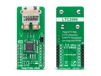
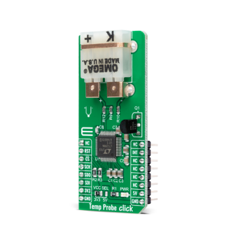
Temp Probe Click is a compact add-on board used as thermocouple temperature monitoring system. This board features the LTC2986, a high accuracy digital temperature measurement system used to directly digitize thermocouples with 0.1°C accuracy and 0.001°C resolution from Analog Devices.

No Abuse Reported

Do you want to subscribe in order to receive notifications regarding "Temp Probe click" changes.

Do you want to unsubscribe in order to stop receiving notifications regarding "Temp Probe click" changes.

Do you want to report abuse regarding "Temp Probe click".
  • mikroSDK Library 2.0.0.0
  • Comments (0)
DOWNLOAD LINK RELATED COMPILER CONTAINS
mikroBasic PRO for ARM
  • lib
  • src
  • exa
  • hlp
  • hex
  • sch
  • pcb
  • doc
mikroBasic PRO for AVR
  • lib
  • src
  • exa
  • hlp
  • hex
  • sch
  • pcb
  • doc
mikroBasic PRO for dsPIC30/33 & PIC24
  • lib
  • src
  • exa
  • hlp
  • hex
  • sch
  • pcb
  • doc
mikroBasic PRO for FT90x
  • lib
  • src
  • exa
  • hlp
  • hex
  • sch
  • pcb
  • doc
mikroBasic PRO for PIC
  • lib
  • src
  • exa
  • hlp
  • hex
  • sch
  • pcb
  • doc
mikroBasic PRO for PIC32
  • lib
  • src
  • exa
  • hlp
  • hex
  • sch
  • pcb
  • doc
mikroC PRO for ARM
  • lib
  • src
  • exa
  • hlp
  • hex
  • sch
  • pcb
  • doc
mikroC PRO for AVR
  • lib
  • src
  • exa
  • hlp
  • hex
  • sch
  • pcb
  • doc
mikroC PRO for dsPIC30/33 & PIC24
  • lib
  • src
  • exa
  • hlp
  • hex
  • sch
  • pcb
  • doc
mikroC PRO for FT90x
  • lib
  • src
  • exa
  • hlp
  • hex
  • sch
  • pcb
  • doc
mikroC PRO for PIC
  • lib
  • src
  • exa
  • hlp
  • hex
  • sch
  • pcb
  • doc
mikroC PRO for PIC32
  • lib
  • src
  • exa
  • hlp
  • hex
  • sch
  • pcb
  • doc
mikroPascal PRO for ARM
  • lib
  • src
  • exa
  • hlp
  • hex
  • sch
  • pcb
  • doc
mikroPascal PRO for AVR
  • lib
  • src
  • exa
  • hlp
  • hex
  • sch
  • pcb
  • doc
mikroPascal PRO for dsPIC30/33 & PIC24
  • lib
  • src
  • exa
  • hlp
  • hex
  • sch
  • pcb
  • doc
mikroPascal PRO for FT90x
  • lib
  • src
  • exa
  • hlp
  • hex
  • sch
  • pcb
  • doc
mikroPascal PRO for PIC
  • lib
  • src
  • exa
  • hlp
  • hex
  • sch
  • pcb
  • doc
mikroPascal PRO for PIC32
  • lib
  • src
  • exa
  • hlp
  • hex
  • sch
  • pcb
  • doc

mikroSDK Library Blog

Temp Probe Click

Temp Probe Click

Native view of the Temp Probe Click board.

View full image
Temp Probe Click

Temp Probe Click

Front and back view of the Temp Probe Click board.

View full image

Library Description

Library performs a control of the Temp Probe Click board™ and performs a configuration on which way temperature be measured. Library offers a choice to measure temperature on the desired channel/channels, depending on the cold junction channel. The device can use a lot of different sensors for measurement, such as thermocouples, diodes, sense resistors, thermistors... For more details check documentation.

Key functions:

  • uint8_t tempprobe_write_byte( uint16_t reg_addr, uint8_t data_in ) - .
  • uint8_t tempprobe_read_word( uint16_t reg_addr, uint32_t *data_out ) - .
  • uint8_t tempprobe_write_eeprom( void ) - Function writes the current settings from the chip registers to the EEPROM memory and checks is error occurred.
  • uint8_t tempprobe_read_temp( uint16_t sel_channel, float *data_out ) - Function reads temperature data from the desired channel.

Examples description

The application is composed of three sections :

  • System Initialization - Initializes peripherals and pins.
  • Application Initialization - Initializes SPI interface and performs a device configuration for properly working. Configures the desired channels and offers a choice to choose in which format temperature be measured. Temperature format can be celsius or fahrenheit.
  • Application Task - Allows start of the conversion for the selected (masked) channels and when conversion cycle is done, reads temperature from channel 10, on which the thermocouple type K sensor is connected. The cold junction channel is channel 9, on which sensor measures the ambient temperature.
void application_task ( )
{
    uint8_t check_state;
    
    tempprobe_write_byte( TEMPPROBE_REG_COMM_STATUS, TEMPPROBE_START_CONV  );
    check_state = tempprobe_check_busy( );
    
    while ( check_state != TEMPPROBE_NO_BUSY_STATE )
    {
        check_state = tempprobe_check_busy( );
    }

    mikrobus_logWrite( ">> PN-Junction: ", _LOG_TEXT );
    tempprobe_read_temp( TEMPPROBE_REG_PN_JUNCTION_CONV_RES , &temperature_k );
    FloatToStr( temperature_k, demo_text );
    mikrobus_logWrite( demo_text, _LOG_LINE );

    mikrobus_logWrite(">> Thermo K: ", _LOG_TEXT );
    tempprobe_read_temp( TEMPPROBE_REG_THERMO_K_CONV_RES, &temperature_pn );
    FloatToStr( temperature_pn, demo_text );
    mikrobus_logWrite( demo_text, _LOG_LINE ); 

    Delay_ms( 1500 );
}

Other mikroE Libraries used in the example:

  • Conversions
  • SPI
  • UART

Additional notes and informations

Depending on the development board you are using, you may need USB UART clickUSB UART 2 click or RS232 click to connect to your PC, for development systems with no UART to USB interface available on the board. The terminal available in all MikroElektronika compilers, or any other terminal application of your choice, can be used to read the message.

ALSO FROM THIS AUTHOR

DALI 2 click

5

DALI 2 click offers a simple and reliable interface to DALI and DALI 2 communication bus, making it possible to dive into the world of intelligent lighting.

[Learn More]

Power Monitor Click

0

Power Monitor Click is a compact add-on board that represents an ultra-precise power monitoring solution. This board features the INA228, a digital power monitor with a 20-bit delta-sigma ADC specifically designed for current-sensing applications from Texas Instruments. The INA228 reports current, bus voltage, temperature, power, energy, and charge accumulation while employing a precision ±0.5 % integrated oscillator, all while performing the needed calculations in the background. It can measure a full-scale differential input of ±163.84mV or ±40.96mV across a resistive shunt sense element, with common-mode voltage support up to +85V. This Click board™ is suitable for current-sensing applications in DC-DC converters, power inverters, telecom equipment, industrial measurements, and many more.

[Learn More]

Hall Current 11 Click

0

Hall Current 11 Click is a compact add-on board that provides economical and precise AC or DC current sensing solutions. This board features the TMCS1108A2U, a galvanically isolated Hall-effect current sensor with high accuracy, excellent linearity, and temperature stability from Texas Instruments. The input current flows through an internal 1.8mΩ conductor that generates a magnetic field measured by an integrated Hall-effect sensor. It features a 100V functional isolation working voltage with both unidirectional and bidirectional current sensing. Based on the selected logic voltage VCC, the TMCS1108A2U allows the user to measure current in two appropriate ranges, where after that, can process the output signal in analog or digital form.

[Learn More]