TOP Contributors

  1. MIKROE (2784 codes)
  2. Alcides Ramos (405 codes)
  3. Shawon Shahryiar (307 codes)
  4. jm_palomino (133 codes)
  5. Bugz Bensce (97 codes)
  6. S P (73 codes)
  7. dany (71 codes)
  8. MikroBUS.NET Team (35 codes)
  9. NART SCHINACKOW (34 codes)
  10. Armstrong Subero (27 codes)

Most Downloaded

  1. Timer Calculator (141699 times)
  2. FAT32 Library (74777 times)
  3. Network Ethernet Library (59219 times)
  4. USB Device Library (49226 times)
  5. Network WiFi Library (44999 times)
  6. FT800 Library (44536 times)
  7. GSM click (31200 times)
  8. mikroSDK (30103 times)
  9. microSD click (27586 times)
  10. PID Library (27543 times)
Libstock prefers package manager

Package Manager

We strongly encourage users to use Package manager for sharing their code on Libstock website, because it boosts your efficiency and leaves the end user with no room for error. [more info]

< Back
mikroSDK Library

ADC 7 click

Rating:

5

Author: MIKROE

Last Updated: 2018-08-03

Package Version: 1.0.0.0

mikroSDK Library: 1.0.0.0

Category: ADC

Downloaded: 6196 times

Followed by: 1 user

License: MIT license  

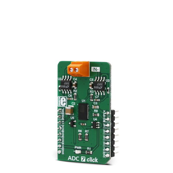
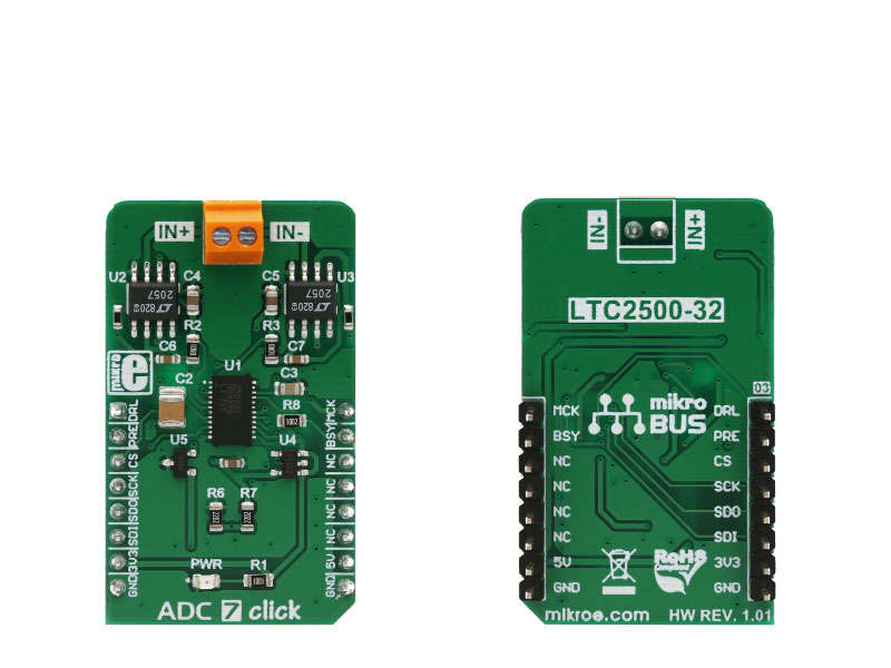
ADC 7 click is an advanced 32-bit analog to digital converter (ADC) which uses the LTC2500-32, a 32-bit oversampling SAR ADC with a configurable digital filter.

No Abuse Reported

Do you want to subscribe in order to receive notifications regarding "ADC 7 click" changes.

Do you want to unsubscribe in order to stop receiving notifications regarding "ADC 7 click" changes.

Do you want to report abuse regarding "ADC 7 click".

  • mikroSDK Library 2.0.0.0
  • Comments (0)
DOWNLOAD LINK RELATED COMPILER CONTAINS
mikroBasic PRO for ARM
  • lib
  • src
  • exa
  • hlp
  • hex
  • sch
  • pcb
  • doc
mikroBasic PRO for AVR
  • lib
  • src
  • exa
  • hlp
  • hex
  • sch
  • pcb
  • doc
mikroBasic PRO for dsPIC30/33 & PIC24
  • lib
  • src
  • exa
  • hlp
  • hex
  • sch
  • pcb
  • doc
mikroBasic PRO for FT90x
  • lib
  • src
  • exa
  • hlp
  • hex
  • sch
  • pcb
  • doc
mikroBasic PRO for PIC
  • lib
  • src
  • exa
  • hlp
  • hex
  • sch
  • pcb
  • doc
mikroBasic PRO for PIC32
  • lib
  • src
  • exa
  • hlp
  • hex
  • sch
  • pcb
  • doc
mikroC PRO for ARM
  • lib
  • src
  • exa
  • hlp
  • hex
  • sch
  • pcb
  • doc
mikroC PRO for AVR
  • lib
  • src
  • exa
  • hlp
  • hex
  • sch
  • pcb
  • doc
mikroC PRO for dsPIC30/33 & PIC24
  • lib
  • src
  • exa
  • hlp
  • hex
  • sch
  • pcb
  • doc
mikroC PRO for FT90x
  • lib
  • src
  • exa
  • hlp
  • hex
  • sch
  • pcb
  • doc
mikroC PRO for PIC
  • lib
  • src
  • exa
  • hlp
  • hex
  • sch
  • pcb
  • doc
mikroC PRO for PIC32
  • lib
  • src
  • exa
  • hlp
  • hex
  • sch
  • pcb
  • doc
mikroPascal PRO for ARM
  • lib
  • src
  • exa
  • hlp
  • hex
  • sch
  • pcb
  • doc
mikroPascal PRO for AVR
  • lib
  • src
  • exa
  • hlp
  • hex
  • sch
  • pcb
  • doc
mikroPascal PRO for dsPIC30/33 & PIC24
  • lib
  • src
  • exa
  • hlp
  • hex
  • sch
  • pcb
  • doc
mikroPascal PRO for FT90x
  • lib
  • src
  • exa
  • hlp
  • hex
  • sch
  • pcb
  • doc
mikroPascal PRO for PIC
  • lib
  • src
  • exa
  • hlp
  • hex
  • sch
  • pcb
  • doc
mikroPascal PRO for PIC32
  • lib
  • src
  • exa
  • hlp
  • hex
  • sch
  • pcb
  • doc

mikroSDK Library Blog

ADC 7 click

ADC 7 click

Native view of the ADC 7 click board.

View full image
ADC 7 click

ADC 7 click

Front and back view of the ADC 7 click board.

View full image

Library Description

The library can perform 32bit AD conversion and can read this 32bit converted voltage value with or without configuration byte/bytes. Library also offers a choice to set configuration for the next conversion cycles. It is not necessary to set configuration for each conversion. A user always can perform conversion cycle/cycles with the last entered configurations. The user can read the converted voltage value as 32bit digital value or as a value calculated in the mV unit. For more details check the documentation.

Key functions:

  • uint8_t adc7_setConfig( uint8_t gainConfig, uint8_t downSampFactor, uint8_t filterType ) - The function performs the device configuration by sending configuration data to configure the next conversion cycle.
  • void adc7_startConvCycle( void ) - The function generates the clock signal on MCK pin and on that way starts and performs the desired number of conversion cycles, determined by Down Sampling Factor number.
  • uint8_t adc7_readResults( int16_t *voltage ) - The function reads 32bit converted voltage value from A/D converter and calculates this value to mV.

Example description

The application is composed of three sections :

  • System Initialization - Initializes peripherals and pins.
  • Application Initialization - Initializes SPI interface and performs configuration for conversion cycles.
  • Application Task - (code snippet) - Performs the determined number of conversion cycles which are necessary for averaging.
void applicationTask()
{
 adc7_startConvCycle();

 while (adc7_checkDataReady() == _ADC7_DATA_NOT_READY);

 adc7_readResults( &voltageData );

 LongToStr( voltageData, text );
 mikrobus_logWrite( "Voltage: ", _LOG_TEXT );
 mikrobus_logWrite( text, _LOG_TEXT );
 mikrobus_logWrite( "mV", _LOG_LINE );

 Delay_ms( 200 );
}


Other mikroE Libraries used in the example:

  • Conversions
  • SPI
  • UART

Additional notes and information

Depending on the development board you are using, you may need USB UART clickUSB UART 2 click or RS232 click to connect to your PC, for development systems with no UART to USB interface available on the board. The terminal available in all MikroElektronika compilers, or any other terminal application of your choice, can be used to read the message.

ALSO FROM THIS AUTHOR

LED Driver 16 Click

0

LED Driver 16 Click is a compact add-on board that simplifies the control of multiple LEDs. This board features the PCA9745B, an SPI-configurable sixteen-channel constant current LED driver from NXP Semiconductors. Each LED output has an 8-bit resolution (256 steps) fixed-frequency individual PWM controller that operates at 31.25kHz with an adjustable duty cycle from 0 to 100% to allow the LED to be set to a specific brightness value. Powered through a selected mikroBUS™ power rail, either 3.3V or 5V, it provides a maximum output current of 57mA per channel and multiple built-in protection functions that protect the circuit during abnormalities.

[Learn More]

Nano Power click

5

Nano Power click is a boost (step-up) DC-DC converter click with extremely high efficiency and very low input voltage, aimed at the low power IoT market and battery-powered sensors and other devices.

[Learn More]

SMS Home Alarm 2

5

This is revised SMS Home Alarm System project with new parts and old function - catch the intruder. When motion sensor detects a movement SMS will be sent to predefined number. If movement is still detectable after disarming delay, Siren or any other device can be activated with help of Relay click.

[Learn More]