TOP Contributors

  1. MIKROE (2784 codes)
  2. Alcides Ramos (405 codes)
  3. Shawon Shahryiar (307 codes)
  4. jm_palomino (133 codes)
  5. Bugz Bensce (97 codes)
  6. S P (73 codes)
  7. dany (71 codes)
  8. MikroBUS.NET Team (35 codes)
  9. NART SCHINACKOW (34 codes)
  10. Armstrong Subero (27 codes)

Most Downloaded

  1. Timer Calculator (141696 times)
  2. FAT32 Library (74763 times)
  3. Network Ethernet Library (59209 times)
  4. USB Device Library (49225 times)
  5. Network WiFi Library (44996 times)
  6. FT800 Library (44529 times)
  7. GSM click (31196 times)
  8. mikroSDK (30100 times)
  9. microSD click (27580 times)
  10. PID Library (27539 times)
Libstock prefers package manager

Package Manager

We strongly encourage users to use Package manager for sharing their code on Libstock website, because it boosts your efficiency and leaves the end user with no room for error. [more info]

< Back
mikroSDK Library

Charger 8 click

Rating:

5

Author: MIKROE

Last Updated: 2019-03-14

Package Version: 1.0.0.0

mikroSDK Library: 1.0.0.0

Category: Battery Charger

Downloaded: 5178 times

Not followed.

License: MIT license  

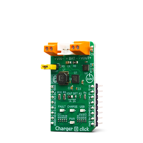
Charger 8 Click is an intelligent Li-Ion battery charger, system power manager, and a battery fuel gauge Click board. As a system power distributor, it can supply up to 2A to a connected load.

No Abuse Reported

Do you want to subscribe in order to receive notifications regarding "Charger 8 click" changes.

Do you want to unsubscribe in order to stop receiving notifications regarding "Charger 8 click" changes.

Do you want to report abuse regarding "Charger 8 click".

  • mikroSDK Library 2.0.0.0
  • Comments (0)
DOWNLOAD LINK RELATED COMPILER CONTAINS
mikroBasic PRO for ARM
  • lib
  • src
  • exa
  • hlp
  • hex
  • sch
  • pcb
  • doc
mikroBasic PRO for AVR
  • lib
  • src
  • exa
  • hlp
  • hex
  • sch
  • pcb
  • doc
mikroBasic PRO for dsPIC30/33 & PIC24
  • lib
  • src
  • exa
  • hlp
  • hex
  • sch
  • pcb
  • doc
mikroBasic PRO for FT90x
  • lib
  • src
  • exa
  • hlp
  • hex
  • sch
  • pcb
  • doc
mikroBasic PRO for PIC
  • lib
  • src
  • exa
  • hlp
  • hex
  • sch
  • pcb
  • doc
mikroBasic PRO for PIC32
  • lib
  • src
  • exa
  • hlp
  • hex
  • sch
  • pcb
  • doc
mikroC PRO for ARM
  • lib
  • src
  • exa
  • hlp
  • hex
  • sch
  • pcb
  • doc
mikroC PRO for AVR
  • lib
  • src
  • exa
  • hlp
  • hex
  • sch
  • pcb
  • doc
mikroC PRO for dsPIC30/33 & PIC24
  • lib
  • src
  • exa
  • hlp
  • hex
  • sch
  • pcb
  • doc
mikroC PRO for FT90x
  • lib
  • src
  • exa
  • hlp
  • hex
  • sch
  • pcb
  • doc
mikroC PRO for PIC
  • lib
  • src
  • exa
  • hlp
  • hex
  • sch
  • pcb
  • doc
mikroC PRO for PIC32
  • lib
  • src
  • exa
  • hlp
  • hex
  • sch
  • pcb
  • doc
mikroPascal PRO for ARM
  • lib
  • src
  • exa
  • hlp
  • hex
  • sch
  • pcb
  • doc
mikroPascal PRO for AVR
  • lib
  • src
  • exa
  • hlp
  • hex
  • sch
  • pcb
  • doc
mikroPascal PRO for dsPIC30/33 & PIC24
  • lib
  • src
  • exa
  • hlp
  • hex
  • sch
  • pcb
  • doc
mikroPascal PRO for FT90x
  • lib
  • src
  • exa
  • hlp
  • hex
  • sch
  • pcb
  • doc
mikroPascal PRO for PIC
  • lib
  • src
  • exa
  • hlp
  • hex
  • sch
  • pcb
  • doc
mikroPascal PRO for PIC32
  • lib
  • src
  • exa
  • hlp
  • hex
  • sch
  • pcb
  • doc

mikroSDK Library Blog

Charger 8 click

Charger 8 click

Native view of the Charger 8 Click board.

View full image
Charger 8 click

Charger 8 click

Front and back view of the Charger 8 Click board.

View full image

Library Description

The library initializes and defines the I2C bus driver and drivers that offer a choice for writing data in register/NV memory and reading data from register/NV memory. The library includes function to read the battery diagnostics. The user can set the maximum battery capacity to have a good reading of the current capacity of the battery. The user has a function for enable/ disable device, sets Alert mode and usb suspand mode.

Key functions:

  • void charger8_enable(uint8_t enable) - Functions for enable or disable device.
  • float charger8_getCurrent() - Functions for reading the current charging battery.
  • float charger8_getVoltage() - Functions for reading the voltage of the battery.
  • void charger8_reset() - General reset procedure.

Examples description

The application is composed of the three sections :

  • System Initialization - Initializes I2C module and sets CS pin, RST pin and PWM pin as OUTPUT and INT pin as INPUT.
  • Application Initialization - Initialization driver init, enable moduele and default configuration, disable ALERT and USB suspand mode and sets max battery capacity.
  • Application Task - (code snippet) - Reads battery diagnostics and this data logs to USBUART every 1500 ms.

Note: The user can charge a battery internally over mikroBUS or externally by supplying the VIN connectors with 5V. For more precise diagnosis and easier tracking of the charging battery status you can set its capacity - e.g. if you have a 2000mAh battery you can use the "charger8_setMaxBatteryCapacity()" function and pass the parameter for 2000mAh, by doing this you make the readings more precise. In the example we used only some possibilities of the diagnostics like temperature of the chip during charging, charging current, current battery voltage, current battery capacity and how much the battery is charged in percentage. In case of changing the battery to a different one, it is neccessary to reset the device and set the battery's maximum capacity.

void applicationTask()
{
    float Temperature;
    float Current;
    float Voltage;
    uint8_t SOC;
    uint16_t Capacity;
    char demoText[50];
    
    mikrobus_logWrite(" - Battery diagnostics - ", _LOG_LINE);
    /* Temperature */
    Temperature = charger8_getTemperature();
    FloatToStr(Temperature, demoText);
    mikrobus_logWrite(" - Temperature : ", _LOG_TEXT);
    mikrobus_logWrite(demoText, _LOG_TEXT);
    mikrobus_logWrite(" C ", _LOG_LINE);
    /* Current */
    Current = charger8_getCurrent();
    FloatToStr(Current, demoText);
    mikrobus_logWrite(" - Current : ", _LOG_TEXT);
    mikrobus_logWrite(demoText, _LOG_TEXT);
    mikrobus_logWrite(" mA ", _LOG_LINE);
    /* Voltage */
    Voltage = charger8_getVoltage();
    FloatToStr(Voltage, demoText);
    mikrobus_logWrite(" - Voltage : ", _LOG_TEXT);
    mikrobus_logWrite(demoText, _LOG_TEXT);
    mikrobus_logWrite(" mV ", _LOG_LINE);
    /* Capacity */
    Capacity = charger8_getCapacity();
    IntToStr(Capacity, demoText);
    mikrobus_logWrite(" - Capacity : ", _LOG_TEXT);
    mikrobus_logWrite(demoText, _LOG_TEXT);
    mikrobus_logWrite(" mAh ", _LOG_LINE);
    /* SOC */
    SOC = charger8_getSOC();
    IntToStr(SOC, demoText);
    mikrobus_logWrite(" - SOC : ", _LOG_TEXT);
    mikrobus_logWrite(demoText, _LOG_TEXT);
    mikrobus_logWrite(" % ", _LOG_LINE);
    
    mikrobus_logWrite(" -------------------------- ", _LOG_LINE);
    Delay_ms( 1500 );
}

Other mikroE Libraries used in the example:

  • I2C
  • UART
  • Conversions

Additional notes and informations

Depending on the development board you are using, you may need USB UART click, USB UART 2 click or RS232 click to connect to your PC, for development systems with no UART to USB interface available on the board. The terminal available in all MikroElektronika compilers, or any other terminal application of your choice, can be used to read the message.

ALSO FROM THIS AUTHOR

LR 10 Click

0

LR 10 Click is a compact add-on board designed for the Internet of Things (IoT) applications requiring low power consumption and long-range connectivity. This board features the Wio-E5, a LoRa wireless module from Seeed Technology. The Wio-E5 integrates the STM32WLE5JC system-level chip and the SX126X LoRa® chip alongside an Arm® Cortex® M4 MCU, ensuring ultra-low power usage and high performance. It supports multi-mode operations, including (G)FSK and LoRa®, and can operate across a frequency range of 868 to 928MHz with robust signal strength and sensitivity. These characteristics make the LR 10 Click ideal for various IoT scenarios, such as wireless sensor networks, remote meter readings, and other applications with crucial low-power, wide-area network connectivity.

[Learn More]

ROTARY O Click

0

Rotary Click carries a 15-pulse incremental rotary encoder with detents, surrounded by a ring of 16 orange LEDs. It’s a perfect solution for adding a precision input knob to your design. The encoder outputs A and B signals (out of phase to each other); the knob also acts as a push-button which sends an interrupt to the target board MCU. The LED ring is controlled through SPI lines (CS, SCK, MISO, MOSI). Rotary Click can be used with either a 3.3V or 5V power supply.

[Learn More]

DALI 2 click

5

DALI 2 click offers a simple and reliable interface to DALI and DALI 2 communication bus, making it possible to dive into the world of intelligent lighting.

[Learn More]