TOP Contributors

  1. MIKROE (2784 codes)
  2. Alcides Ramos (404 codes)
  3. Shawon Shahryiar (307 codes)
  4. jm_palomino (132 codes)
  5. Bugz Bensce (97 codes)
  6. S P (73 codes)
  7. dany (71 codes)
  8. MikroBUS.NET Team (35 codes)
  9. NART SCHINACKOW (34 codes)
  10. Armstrong Subero (27 codes)

Most Downloaded

  1. Timer Calculator (141012 times)
  2. FAT32 Library (73548 times)
  3. Network Ethernet Library (58369 times)
  4. USB Device Library (48553 times)
  5. Network WiFi Library (44174 times)
  6. FT800 Library (43707 times)
  7. GSM click (30581 times)
  8. mikroSDK (29340 times)
  9. PID Library (27221 times)
  10. microSD click (26969 times)
Libstock prefers package manager

Package Manager

We strongly encourage users to use Package manager for sharing their code on Libstock website, because it boosts your efficiency and leaves the end user with no room for error. [more info]

< Back
mikroSDK Library

Pedometer click

Rating:

5

Author: MIKROE

Last Updated: 2019-06-18

Package Version: 1.0.0.0

mikroSDK Library: 1.0.0.0

Category: Motion

Downloaded: 3224 times

Not followed.

License: MIT license  

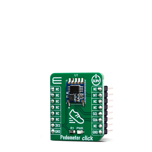
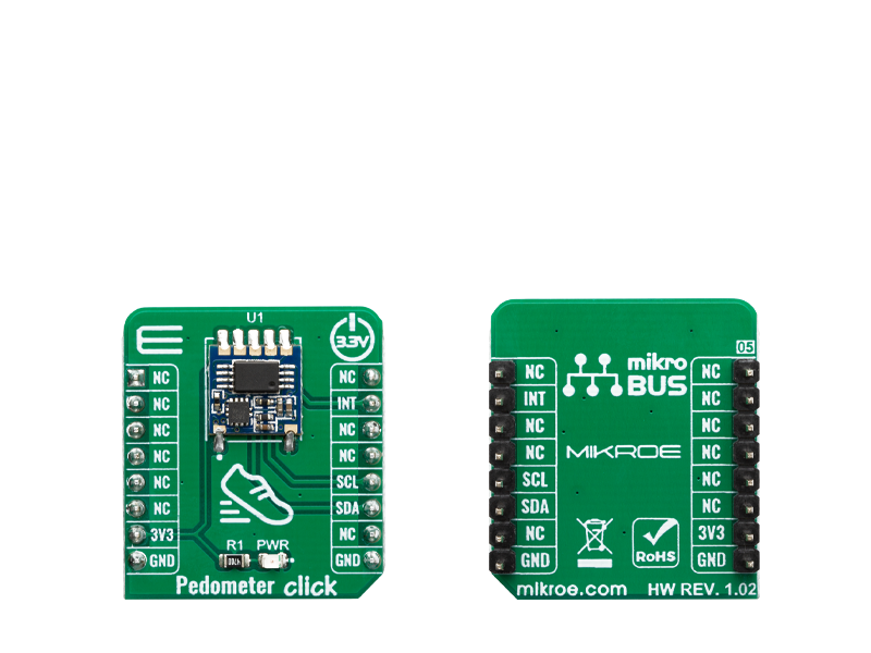
Pedometer Click is designed to sense movement, more precisely, to sense and count steps taken by its user. It is equipped with the STP201M module, a 3D pedometer module with an IC chipset, which includes a precise G-sensor and MCU.

No Abuse Reported

Do you want to subscribe in order to receive notifications regarding "Pedometer click" changes.

Do you want to unsubscribe in order to stop receiving notifications regarding "Pedometer click" changes.

Do you want to report abuse regarding "Pedometer click".

  • mikroSDK Library 2.0.0.0
  • Comments (0)
DOWNLOAD LINK RELATED COMPILER CONTAINS
mikroBasic PRO for ARM
  • lib
  • src
  • exa
  • hlp
  • hex
  • sch
  • pcb
  • doc
mikroBasic PRO for AVR
  • lib
  • src
  • exa
  • hlp
  • hex
  • sch
  • pcb
  • doc
mikroBasic PRO for dsPIC30/33 & PIC24
  • lib
  • src
  • exa
  • hlp
  • hex
  • sch
  • pcb
  • doc
mikroBasic PRO for PIC
  • lib
  • src
  • exa
  • hlp
  • hex
  • sch
  • pcb
  • doc
mikroBasic PRO for PIC32
  • lib
  • src
  • exa
  • hlp
  • hex
  • sch
  • pcb
  • doc
mikroC PRO for ARM
  • lib
  • src
  • exa
  • hlp
  • hex
  • sch
  • pcb
  • doc
mikroC PRO for AVR
  • lib
  • src
  • exa
  • hlp
  • hex
  • sch
  • pcb
  • doc
mikroC PRO for dsPIC30/33 & PIC24
  • lib
  • src
  • exa
  • hlp
  • hex
  • sch
  • pcb
  • doc
mikroC PRO for PIC
  • lib
  • src
  • exa
  • hlp
  • hex
  • sch
  • pcb
  • doc
mikroC PRO for PIC32
  • lib
  • src
  • exa
  • hlp
  • hex
  • sch
  • pcb
  • doc
mikroPascal PRO for ARM
  • lib
  • src
  • exa
  • hlp
  • hex
  • sch
  • pcb
  • doc
mikroPascal PRO for AVR
  • lib
  • src
  • exa
  • hlp
  • hex
  • sch
  • pcb
  • doc
mikroPascal PRO for dsPIC30/33 & PIC24
  • lib
  • src
  • exa
  • hlp
  • hex
  • sch
  • pcb
  • doc
mikroPascal PRO for PIC
  • lib
  • src
  • exa
  • hlp
  • hex
  • sch
  • pcb
  • doc
mikroPascal PRO for PIC32
  • lib
  • src
  • exa
  • hlp
  • hex
  • sch
  • pcb
  • doc

mikroSDK Library Blog

Pedometer click

Pedometer click

Native view of the Pedometer click board.

View full image
Pedometer click

Pedometer click

Front and back view of the Pedometer click board.

View full image

Library Description

The library contains all the necessary functions for detecting and reading the steps.

Key functions:

  • uint8_t pedometer_process() - Pedometer process.
  • uint32_t pedometer_getStepCounter() - Functions for get step counter.
  • void pedometer_resetStepCounter(uint32_t newCnt) - Functions for reset Step counter.

Examples description

The application is composed of three sections :

  • System Initialization - Sets INT pin as INPUT for detection STEP .
  • Application Initialization - Initializes driver init and sets step counter on 0 .
  • Application Task - It checks if a new step is detected, if detected new step - reads the current number of steps made and logs data to the USBUART.
void applicationTask()
{
    uint8_t newStep;
    uint32_t stepCounter;
    char demoText[ 50 ];
    
    newStep = pedometer_process();

    if(newStep == PEDOMETER_NEW_STEP_DETECTED)
    {
        stepCounter = pedometer_getStepCounter();
        LongWordToStr(stepCounter, demoText);
        mikrobus_logWrite(" Step Counter : ", _LOG_TEXT);
        mikrobus_logWrite(demoText, _LOG_LINE);
        
        mikrobus_logWrite("---------------------------", _LOG_LINE);
        Delay_ms( 50 );
    }
}

Other mikroE Libraries used in the example:

  • Conversions Library
  • UART Library

Additional notes and informations

Depending on the development board you are using, you may need USB UART clickUSB UART 2 click or RS232 click to connect to your PC, for development systems with no UART to USB interface available on the board. The terminal available in all MikroElektronika compilers, or any other terminal application of your choice, can be used to read the message.

ALSO FROM THIS AUTHOR

UV 5 Click

0

UV 5 Click is a compact add-on board that can measure UV radiation. This board features the AS7331, a spectral UVA/B/C sensor from ams. The sensor can measure UVA, UVB, and UVC, which are the main types of UV rays from the UV radiation of the sunlight. It uses ADC with a high dynamic range (16… 24-bit) for measurements from low to high radiation conditions and has a high sensitivity, which makes it usable for fluorescence light conditions.

[Learn More]

Button R Click

0

Button R Click is the simplest solution for adding a single pushbutton to your design. The button itself is transparent, 6.8mm in diameter and has a red LED backlight. When pressed, it sends an interrupt signal to the target board microcontroller. The backlight LED is controlled separately through the mikroBUS PWM pin, so you can program all kinds of patterns (varying level of light intensity or rate of blinking on subsequent button presses). The board can use either a 3.3V or a 5V power supply.

[Learn More]

FTDI click - Example

0

This is demonstration project how FTDI click can be used to control slave microcontroller via I2C. Lower nibble of slave address is masked which enables the master to address slave using eight different addresses. Currently four addresses are implemented for different functionality.

[Learn More]