TOP Contributors

  1. MIKROE (2751 codes)
  2. Alcides Ramos (372 codes)
  3. Shawon Shahryiar (307 codes)
  4. jm_palomino (118 codes)
  5. Bugz Bensce (90 codes)
  6. S P (73 codes)
  7. dany (71 codes)
  8. MikroBUS.NET Team (35 codes)
  9. NART SCHINACKOW (34 codes)
  10. Armstrong Subero (27 codes)

Most Downloaded

  1. Timer Calculator (139058 times)
  2. FAT32 Library (71588 times)
  3. Network Ethernet Library (56988 times)
  4. USB Device Library (47330 times)
  5. Network WiFi Library (43006 times)
  6. FT800 Library (42297 times)
  7. GSM click (29774 times)
  8. mikroSDK (27874 times)
  9. PID Library (26858 times)
  10. microSD click (26129 times)
Libstock prefers package manager

Package Manager

We strongly encourage users to use Package manager for sharing their code on Libstock website, because it boosts your efficiency and leaves the end user with no room for error. [more info]

< Back
mikroSDK Library

Charger 9 click

Rating:

5

Author: MIKROE

Last Updated: 2019-05-27

Package Version: 1.0.0.0

mikroSDK Library: 1.0.0.0

Category: Battery Charger

Downloaded: 3654 times

Not followed.

License: MIT license  

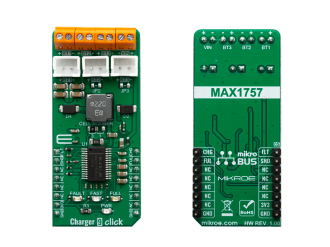
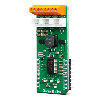
Charger 9 click is a Li-Ion (Li+, Li-Po) battery charger, capable of charging one, two or three battery cells. It is based on the MAX1757, an integrated Li+ battery charger with many features that allow safe and reliable charging.

No Abuse Reported

Do you want to subscribe in order to receive notifications regarding "Charger 9 click" changes.

Do you want to unsubscribe in order to stop receiving notifications regarding "Charger 9 click" changes.

Do you want to report abuse regarding "Charger 9 click".
  • mikroSDK Library 2.0.0.0
  • Comments (0)
DOWNLOAD LINK RELATED COMPILER CONTAINS
mikroBasic PRO for ARM
  • lib
  • src
  • exa
  • hlp
  • hex
  • sch
  • pcb
  • doc
mikroBasic PRO for AVR
  • lib
  • src
  • exa
  • hlp
  • hex
  • sch
  • pcb
  • doc
mikroBasic PRO for dsPIC30/33 & PIC24
  • lib
  • src
  • exa
  • hlp
  • hex
  • sch
  • pcb
  • doc
mikroBasic PRO for FT90x
  • lib
  • src
  • exa
  • hlp
  • hex
  • sch
  • pcb
  • doc
mikroBasic PRO for PIC
  • lib
  • src
  • exa
  • hlp
  • hex
  • sch
  • pcb
  • doc
mikroBasic PRO for PIC32
  • lib
  • src
  • exa
  • hlp
  • hex
  • sch
  • pcb
  • doc
mikroC PRO for ARM
  • lib
  • src
  • exa
  • hlp
  • hex
  • sch
  • pcb
  • doc
mikroC PRO for AVR
  • lib
  • src
  • exa
  • hlp
  • hex
  • sch
  • pcb
  • doc
mikroC PRO for dsPIC30/33 & PIC24
  • lib
  • src
  • exa
  • hlp
  • hex
  • sch
  • pcb
  • doc
mikroC PRO for FT90x
  • lib
  • src
  • exa
  • hlp
  • hex
  • sch
  • pcb
  • doc
mikroC PRO for PIC
  • lib
  • src
  • exa
  • hlp
  • hex
  • sch
  • pcb
  • doc
mikroC PRO for PIC32
  • lib
  • src
  • exa
  • hlp
  • hex
  • sch
  • pcb
  • doc
mikroPascal PRO for ARM
  • lib
  • src
  • exa
  • hlp
  • hex
  • sch
  • pcb
  • doc
mikroPascal PRO for AVR
  • lib
  • src
  • exa
  • hlp
  • hex
  • sch
  • pcb
  • doc
mikroPascal PRO for dsPIC30/33 & PIC24
  • lib
  • src
  • exa
  • hlp
  • hex
  • sch
  • pcb
  • doc
mikroPascal PRO for FT90x
  • lib
  • src
  • exa
  • hlp
  • hex
  • sch
  • pcb
  • doc
mikroPascal PRO for PIC
  • lib
  • src
  • exa
  • hlp
  • hex
  • sch
  • pcb
  • doc
mikroPascal PRO for PIC32
  • lib
  • src
  • exa
  • hlp
  • hex
  • sch
  • pcb
  • doc

mikroSDK Library Blog

Charger 9 click

Charger 9 click

Native view of the Charger 9 click board.

View full image
Charger 9 click

Charger 9 click

Front and back view of the Charger 9 click board.

View full image

Library Description

This library allows user to perform a control of the Charger 9 Click board. Also user can check the indication status from the charger to get charging state. Fault condition also can be checked. For more details check documentation.

Key functions:

  • void charger9_gpioDriverInit(T_CHARGER9_P gpioObj) - Convert ADC value to Pressure data in mBar.
  • T_CHARGER9_RETVAL charger9_enable( T_CHARGER9_STATE pwr_state ) - Convert ADC value to Voltage in mV.
  • T_CHARGER9_RETVAL charger9_faultInd( void ) - Sets max output voltage on the AN pin.

Examples description

The application is composed of three sections :

  • System Initialization - Initializes peripherals and pins.
  • Application Initialization - Initializes GPIO driver and turns OFF the charger as initial state.
  • Application Task - (code snippet) - Checks which command was sent by user and performs the selected command. Also checks the fault condition, and when fault condition is detected sends a report message to the uart terminal and turns OFF the charger. Note: When user sends a desired command to the charger, a report message will be sent to the uart terminal as indication to the user. The possible commands, for Charger 9 control, will be written to the uart terminal. The alarm sound will be generated on the determined commands: enable, disable and fault condition detecting.
void applicationTask()
{
	rx_dat = UART_Rdy_Ptr();
	
	if (rx_dat != 0)
	{
		rx_dat = UART_Rd_Ptr();
		
		switch (rx_dat)
		{
			case 'e' :
			{
				if (en_flag == _CHARGER9_DISABLE)
				{
					charger9_enable( _CHARGER9_ENABLE );
					en_flag = _CHARGER9_ENABLE;
					
					mikrobus_logWrite( "** Charger 9 is enabled **", _LOG_LINE );
					alarmOn();
				}
				else
				{
					mikrobus_logWrite( "** Charger 9 is already enabled **", _LOG_LINE );
				}
			break;
			}
			case 'd' :
			{
				if (en_flag == _CHARGER9_ENABLE)
				{
					charger9_enable( _CHARGER9_DISABLE );
					en_flag = _CHARGER9_DISABLE;

					mikrobus_logWrite( "** Charger 9 is disabled **", _LOG_LINE );
					alarmOff();
				}
				else
				{
					mikrobus_logWrite( "** Charger 9 is already disabled **", _LOG_LINE );
				}
			break;
			}
			case 's' :
			{
				charge_state = charger9_fullChargeInd();
				
				if (charge_state == _CHARGER9_IND_ACTIVE)
				{
					mikrobus_logWrite( "** Full-Charge state **", _LOG_LINE );
				}
				
				charge_state = charger9_fastChargeInd();

				if (charge_state == _CHARGER9_IND_ACTIVE)
				{
					mikrobus_logWrite( "** Fast-Charge state **", _LOG_LINE );
				}
			break;
			}
			case 'l' :
			{
				writeLegend();
			break;
			}
			default :
			{
				mikrobus_logWrite( "** Invalid command **", _LOG_LINE );
				writeLegend();
			break;
			}
		}
	}
	
	charge_state = charger9_faultInd();
	
	if (charge_state == _CHARGER9_IND_ACTIVE)
	{
		charger9_enable( _CHARGER9_DISABLE );
		en_flag = _CHARGER9_DISABLE;
		
		mikrobus_logWrite( "** Fault condition! **", _LOG_LINE );
		mikrobus_logWrite( "** Charger 9 is disabled **", _LOG_LINE );
		alarmFault();
	}
}
			

Additional Functions :

  • alarmOn - Generates an alarm sound for charger power ON.
  • alarmOff - Generates an alarm sound for charger power OFF.
  • alarmFault - Generates an alarm sound for fault condition.
  • writeLegend - Writes possible valid commands to the uart terminal.

Other mikroE Libraries used in the example:

  • Sound
  • UART

Additional notes and informations

Depending on the development board you are using, you may need USB UART clickUSB UART 2 click or RS232 click to connect to your PC, for development systems with no UART to USB interface available on the board. The terminal available in all MikroElektronika compilers, or any other terminal application of your choice, can be used to read the message.

ALSO FROM THIS AUTHOR

IPS Display Click

0

IPS Display Click is a compact add-on board that displays high-resolution graphics in embedded applications. This board features the ER-TFT1.14-2, a 1.14inch TFT LCD display from BuyDisplay, part of EastRising Technology, and utilizes the ST7789V controller for 262K color output. The display offers a 135x240 pixel resolution, operates through a 3-wire SPI interface, and includes additional control lines such as RST and RS for precise display management. Its small form factor and high-resolution output make it suitable for various projects, including handheld devices, smart displays, and control panels requiring clear visual output.

[Learn More]

EEG Click

0

EEG Click is a Click board™ that allows monitoring of brain activity. Although not suitable for clinical examination, it is quite sufficient to allow some insight into brain activity. EEG Click is equipped with a high-sensitivity circuit which amplifies faint electrical signals from the brain, allowing them to be sampled by a host MCU.

[Learn More]

SPIRIT Click

0

SPIRIT Click carries the SP1ML 868MHz ultra low-power RF module. The board is designed to use 3.3V power supply and 3.3V or 5V I/O voltage levels. It communicates with the target MCU over UART interface, with additional functionality provided by the following pins on the mikroBUS™ line: PWM, RST, CS.

[Learn More]