TOP Contributors

  1. MIKROE (2784 codes)
  2. Alcides Ramos (405 codes)
  3. Shawon Shahryiar (307 codes)
  4. jm_palomino (133 codes)
  5. Bugz Bensce (97 codes)
  6. S P (73 codes)
  7. dany (71 codes)
  8. MikroBUS.NET Team (35 codes)
  9. NART SCHINACKOW (34 codes)
  10. Armstrong Subero (27 codes)

Most Downloaded

  1. Timer Calculator (142085 times)
  2. FAT32 Library (75310 times)
  3. Network Ethernet Library (59504 times)
  4. USB Device Library (49526 times)
  5. Network WiFi Library (45290 times)
  6. FT800 Library (44928 times)
  7. GSM click (31442 times)
  8. mikroSDK (30467 times)
  9. microSD click (27804 times)
  10. PID Library (27625 times)
Libstock prefers package manager

Package Manager

We strongly encourage users to use Package manager for sharing their code on Libstock website, because it boosts your efficiency and leaves the end user with no room for error. [more info]

< Back
mikroSDK Library

Buck 12 click

Rating:

5

Author: MIKROE

Last Updated: 2019-07-23

Package Version: 1.0.0.0

mikroSDK Library: 1.0.0.0

Category: Buck

Downloaded: 3753 times

Not followed.

License: MIT license  

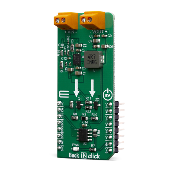
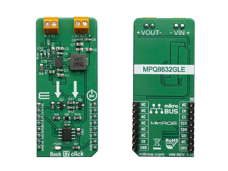
Buck 12 Click is a high-efficiency step-down converter which provides 3.3V on its output, derived from the connected power supply voltage, in the range from 4.2V to 18V.

No Abuse Reported

Do you want to subscribe in order to receive notifications regarding "Buck 12 click" changes.

Do you want to unsubscribe in order to stop receiving notifications regarding "Buck 12 click" changes.

Do you want to report abuse regarding "Buck 12 click".

  • mikroSDK Library 2.0.0.0
  • Comments (0)
DOWNLOAD LINK RELATED COMPILER CONTAINS
mikroBasic PRO for ARM
  • lib
  • src
  • exa
  • hlp
  • hex
  • sch
  • pcb
  • doc
mikroBasic PRO for AVR
  • lib
  • src
  • exa
  • hlp
  • hex
  • sch
  • pcb
  • doc
mikroBasic PRO for dsPIC30/33 & PIC24
  • lib
  • src
  • exa
  • hlp
  • hex
  • sch
  • pcb
  • doc
mikroBasic PRO for FT90x
  • lib
  • src
  • exa
  • hlp
  • hex
  • sch
  • pcb
  • doc
mikroBasic PRO for PIC
  • lib
  • src
  • exa
  • hlp
  • hex
  • sch
  • pcb
  • doc
mikroBasic PRO for PIC32
  • lib
  • src
  • exa
  • hlp
  • hex
  • sch
  • pcb
  • doc
mikroC PRO for ARM
  • lib
  • src
  • exa
  • hlp
  • hex
  • sch
  • pcb
  • doc
mikroC PRO for AVR
  • lib
  • src
  • exa
  • hlp
  • hex
  • sch
  • pcb
  • doc
mikroC PRO for dsPIC30/33 & PIC24
  • lib
  • src
  • exa
  • hlp
  • hex
  • sch
  • pcb
  • doc
mikroC PRO for FT90x
  • lib
  • src
  • exa
  • hlp
  • hex
  • sch
  • pcb
  • doc
mikroC PRO for PIC
  • lib
  • src
  • exa
  • hlp
  • hex
  • sch
  • pcb
  • doc
mikroC PRO for PIC32
  • lib
  • src
  • exa
  • hlp
  • hex
  • sch
  • pcb
  • doc
mikroPascal PRO for ARM
  • lib
  • src
  • exa
  • hlp
  • hex
  • sch
  • pcb
  • doc
mikroPascal PRO for AVR
  • lib
  • src
  • exa
  • hlp
  • hex
  • sch
  • pcb
  • doc
mikroPascal PRO for dsPIC30/33 & PIC24
  • lib
  • src
  • exa
  • hlp
  • hex
  • sch
  • pcb
  • doc
mikroPascal PRO for FT90x
  • lib
  • src
  • exa
  • hlp
  • hex
  • sch
  • pcb
  • doc
mikroPascal PRO for PIC
  • lib
  • src
  • exa
  • hlp
  • hex
  • sch
  • pcb
  • doc
mikroPascal PRO for PIC32
  • lib
  • src
  • exa
  • hlp
  • hex
  • sch
  • pcb
  • doc

mikroSDK Library Blog

Buck 12 click

Buck 12 click

Native view of the Buck 12 click board.

View full image
Buck 12 click

Buck 12 click

Front and back view of the Buck 12 click board.

View full image

Library Description

The library initializes and defines the SPI bus driver. The library includes function for enable or disable buck device. The user also has the function for read voltage on the input and output terminal.

Key functions:

  • void buck12_control(uint8_t ctrl) - Function for enable or disable device.
  • float buck12_getVoltage(uint8_t selectVolt) - Function for get Voltage.

Examples description

The application is composed of three sections :

  • System Initialization - Initializes SPI module and sets CS pin and RST pin as OUTPUT.
  • Application Initialization - Initialization driver init and BUCK enabled.
  • Application Task - Reads the voltage in [mV] at the input and output terminals. This data logs to the USBUART every 2 sec.

Note: Voltage on VIN terminal must be between 2.5V and 18V. When the BUCK is enabled - the voltage on the VOUT terminal is about 3.3V..

void applicationTask()
{
    char demoText[ 20 ];
    float Voltage;

    Voltage = buck12_getVoltage(_BUCK12_INPUT_VOLTAGE);
    
    FloatToStr(Voltage, demoText);
    mikrobus_logWrite("* VIN : ", _LOG_TEXT);
    mikrobus_logWrite(demoText, _LOG_TEXT);
    mikrobus_logWrite(" mV", _LOG_LINE);
    
    Voltage = buck12_getVoltage(_BUCK12_OUTPUT_VOLTAGE);

    FloatToStr(Voltage, demoText);
    mikrobus_logWrite("* VOUT : ", _LOG_TEXT);
    mikrobus_logWrite(demoText, _LOG_TEXT);
    mikrobus_logWrite(" mV", _LOG_LINE);
    
    mikrobus_logWrite("--------------------------", _LOG_LINE);
    Delay_ms( 2000 );
}

Other mikroE Libraries used in the example:

  • SPI
  • UART
  • Conversions

Additional notes and informations

Depending on the development board you are using, you may need USB UART clickUSB UART 2 click or RS232 click to connect to your PC, for development systems with no UART to USB interface available on the board. The terminal available in all MikroElektronika compilers, or any other terminal application of your choice, can be used to read the message.

ALSO FROM THIS AUTHOR

DC Motor 14 Click

0

This IC includes one channel of motor output block, using a wide range of supply voltages, while delivering reasonably high current to the connected DC motors.

[Learn More]

SPIRIT Click

0

SPIRIT Click carries the SP1ML 868MHz ultra low-power RF module. The board is designed to use 3.3V power supply and 3.3V or 5V I/O voltage levels. It communicates with the target MCU over UART interface, with additional functionality provided by the following pins on the mikroBUS™ line: PWM, RST, CS.

[Learn More]

Smart Buck 3 Click

0

Smart Buck 3 Click is a compact add-on board that contains a high-frequency synchronous step-down DC-DC converter. This board features the TPS62366A, a processor supply with I2C compatible interface and a remote sense from Texas Instruments. As input, it uses voltages in the range of 2.5V up to 5.5V, including support for common battery technologies. As output, the converter can scale voltage from 0.5V up to 1.77V in 10mV steps, retaining up to 2.5A peak output current, operating at 2.5MHz of the typical switching frequency.

[Learn More]