TOP Contributors

  1. MIKROE (2784 codes)
  2. Alcides Ramos (405 codes)
  3. Shawon Shahryiar (307 codes)
  4. jm_palomino (133 codes)
  5. Bugz Bensce (97 codes)
  6. S P (73 codes)
  7. dany (71 codes)
  8. MikroBUS.NET Team (35 codes)
  9. NART SCHINACKOW (34 codes)
  10. Armstrong Subero (27 codes)

Most Downloaded

  1. Timer Calculator (141592 times)
  2. FAT32 Library (74544 times)
  3. Network Ethernet Library (59063 times)
  4. USB Device Library (49098 times)
  5. Network WiFi Library (44842 times)
  6. FT800 Library (44399 times)
  7. GSM click (31067 times)
  8. mikroSDK (29943 times)
  9. microSD click (27504 times)
  10. PID Library (27493 times)
Libstock prefers package manager

Package Manager

We strongly encourage users to use Package manager for sharing their code on Libstock website, because it boosts your efficiency and leaves the end user with no room for error. [more info]

< Back
mikroSDK Library

3D Hall 7 click

Rating:

5

Author: MIKROE

Last Updated: 2019-06-27

Package Version: 1.0.0.0

mikroSDK Library: 1.0.0.0

Category: Magnetic

Downloaded: 3702 times

Not followed.

License: MIT license  

3D HALL 7 click is a very accurate, magnetic field sensing Click board, used to measure the intensity of the magnetic field across three perpendicular axes.

No Abuse Reported

Do you want to subscribe in order to receive notifications regarding "3D Hall 7 click" changes.

Do you want to unsubscribe in order to stop receiving notifications regarding "3D Hall 7 click" changes.

Do you want to report abuse regarding "3D Hall 7 click".
  • mikroSDK Library 2.0.0.0
  • Comments (0)
DOWNLOAD LINK RELATED COMPILER CONTAINS
mikroBasic PRO for ARM
  • lib
  • src
  • exa
  • hlp
  • hex
  • sch
  • pcb
  • doc
mikroBasic PRO for AVR
  • lib
  • src
  • exa
  • hlp
  • hex
  • sch
  • pcb
  • doc
mikroBasic PRO for dsPIC30/33 & PIC24
  • lib
  • src
  • exa
  • hlp
  • hex
  • sch
  • pcb
  • doc
mikroBasic PRO for FT90x
  • lib
  • src
  • exa
  • hlp
  • hex
  • sch
  • pcb
  • doc
mikroBasic PRO for PIC
  • lib
  • src
  • exa
  • hlp
  • hex
  • sch
  • pcb
  • doc
mikroBasic PRO for PIC32
  • lib
  • src
  • exa
  • hlp
  • hex
  • sch
  • pcb
  • doc
mikroC PRO for ARM
  • lib
  • src
  • exa
  • hlp
  • hex
  • sch
  • pcb
  • doc
mikroC PRO for AVR
  • lib
  • src
  • exa
  • hlp
  • hex
  • sch
  • pcb
  • doc
mikroC PRO for dsPIC30/33 & PIC24
  • lib
  • src
  • exa
  • hlp
  • hex
  • sch
  • pcb
  • doc
mikroC PRO for FT90x
  • lib
  • src
  • exa
  • hlp
  • hex
  • sch
  • pcb
  • doc
mikroC PRO for PIC
  • lib
  • src
  • exa
  • hlp
  • hex
  • sch
  • pcb
  • doc
mikroC PRO for PIC32
  • lib
  • src
  • exa
  • hlp
  • hex
  • sch
  • pcb
  • doc
mikroPascal PRO for ARM
  • lib
  • src
  • exa
  • hlp
  • hex
  • sch
  • pcb
  • doc
mikroPascal PRO for AVR
  • lib
  • src
  • exa
  • hlp
  • hex
  • sch
  • pcb
  • doc
mikroPascal PRO for dsPIC30/33 & PIC24
  • lib
  • src
  • exa
  • hlp
  • hex
  • sch
  • pcb
  • doc
mikroPascal PRO for FT90x
  • lib
  • src
  • exa
  • hlp
  • hex
  • sch
  • pcb
  • doc
mikroPascal PRO for PIC
  • lib
  • src
  • exa
  • hlp
  • hex
  • sch
  • pcb
  • doc
mikroPascal PRO for PIC32
  • lib
  • src
  • exa
  • hlp
  • hex
  • sch
  • pcb
  • doc

mikroSDK Library Blog

3D Hall 7 click

3D Hall 7 click

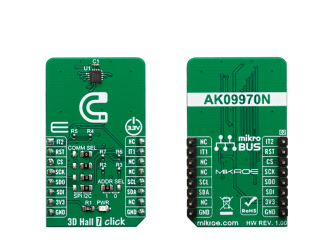
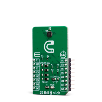
Native view of the 3D Hall 7 click board.

View full image
3D Hall 7 click

3D Hall 7 click

Front and back view of the 3D Hall 7 click board.

View full image

Library Description

The library initializes and defines the I2C bus or SPI bus driver and drivers that offer a choice for writing data in register and reads data from register. The library includes function for read magnetics X/Y/Z axis data, configuration device, reads interrupt states and device info(company ID and device ID).

Key functions:

  • void c3dhall7_getAxisData( T_C3DHALL7_AXIS *axis) - Get Axis data.
  • void c3dhall7_configuration(uint8_t reg, uint16_t dataIn) - Configuration function.

Examples description

The application is composed of the three sections :

  • System Initialization - Initializes I2C or SPI module and all the necessary GPIO pins.
  • Application Initialization - Initializes driver init, test communication and configuration device for measurement.
  • Application Task - Reads 3 Axis of the magnetic sensor and logs this data to USBUART every 500ms.
void applicationTask()
{
    char demoText[ 50 ];
    
    c3dhall7_getAxisData(&axis);
    
    mikrobus_logWrite("---- Measurement data of magnetic sensor ----", _LOG_LINE);
    IntToStr(axis.x, demoText);
    mikrobus_logWrite("** X axis: ", _LOG_TEXT);
    mikrobus_logWrite(demoText, _LOG_LINE);
    
    IntToStr(axis.y, demoText);
    mikrobus_logWrite("** Y axis: ", _LOG_TEXT);
    mikrobus_logWrite(demoText, _LOG_LINE);
    
    IntToStr(axis.z, demoText);
    mikrobus_logWrite("** Z axis: ", _LOG_TEXT);
    mikrobus_logWrite(demoText, _LOG_LINE);
    
    mikrobus_logWrite("---------------------------------------------", _LOG_LINE);
    Delay_ms( 500 );
}

Other mikroE Libraries used in the example:

  • SPI Library
  • I2C Library
  • UART Library
  • Conversions Library

Additional notes and informations

Depending on the development board you are using, you may need USB UART clickUSB UART 2 click or RS232 click to connect to your PC, for development systems with no UART to USB interface available on the board. The terminal available in all MikroElektronika compilers, or any other terminal application of your choice, can be used to read the message.

ALSO FROM THIS AUTHOR

External Memory

22

Contains libraries for working with 24C02 EEPROM memory, low-voltage serial flash memory M25P80 and serial SRAM 23K640 device.

[Learn More]

Flicker click

0

FLICKER click is perfect, simple solution if you need to turn a device on and off at specific time intervals, like blinking LED commercials, alarm system lights, or any other signalling lights. This example shows how by using the button you can start time relay and configure it's duration of on and off period.

[Learn More]

4x4 RGB 2 Click

0

4x4 RGB 2 Click is a compact add-on board that contains a matrix of 16 intelligent RGB LEDs, forming a 4x4 display screen. This board features 16 IN-PC55TBTRGB, 5x5mm RGB LEDs with an integrated IC from Inolux. The LEDs feature an 8-bit color control in 256 steps (256-level greyscale) and a 5-bit brightness control in 32 steps. The intelligent LEDs are cascaded (daisy-chained); thus, every one of them can communicate with the host MCU using the same data lines.

[Learn More]