TOP Contributors

  1. MIKROE (2784 codes)
  2. Alcides Ramos (405 codes)
  3. Shawon Shahryiar (307 codes)
  4. jm_palomino (133 codes)
  5. Bugz Bensce (97 codes)
  6. S P (73 codes)
  7. dany (71 codes)
  8. MikroBUS.NET Team (35 codes)
  9. NART SCHINACKOW (34 codes)
  10. Armstrong Subero (27 codes)

Most Downloaded

  1. Timer Calculator (141304 times)
  2. FAT32 Library (74107 times)
  3. Network Ethernet Library (58718 times)
  4. USB Device Library (48830 times)
  5. Network WiFi Library (44526 times)
  6. FT800 Library (44078 times)
  7. GSM click (30834 times)
  8. mikroSDK (29673 times)
  9. PID Library (27357 times)
  10. microSD click (27251 times)
Libstock prefers package manager

Package Manager

We strongly encourage users to use Package manager for sharing their code on Libstock website, because it boosts your efficiency and leaves the end user with no room for error. [more info]

< Back
mikroSDK Library

M-BUS RF 4 click

Rating:

5

Author: MIKROE

Last Updated: 2019-10-14

Package Version: 1.0.0.0

mikroSDK Library: 1.0.0.0

Category: Sub-1 GHz Transceivers

Downloaded: 4075 times

Not followed.

License: MIT license  

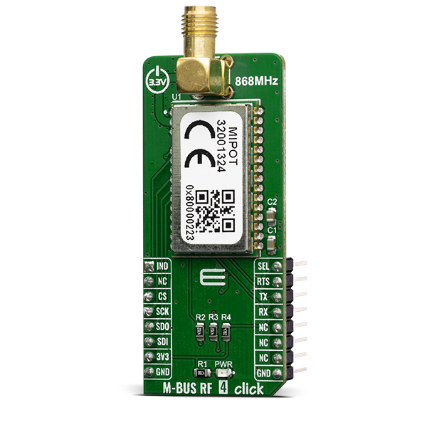
M-BUS RF 4 Click is a mikroBUS add-on board with a MIPOT 32001324 RF wireless transceiver. This module operates in the 868 MHz SRD Band.

No Abuse Reported

Do you want to subscribe in order to receive notifications regarding "M-BUS RF 4 click" changes.

Do you want to unsubscribe in order to stop receiving notifications regarding "M-BUS RF 4 click" changes.

Do you want to report abuse regarding "M-BUS RF 4 click".

  • mikroSDK Library 2.0.0.0
  • Comments (0)
DOWNLOAD LINK RELATED COMPILER CONTAINS
mikroBasic PRO for ARM
  • lib
  • src
  • exa
  • hlp
  • hex
  • sch
  • pcb
  • doc
mikroBasic PRO for AVR
  • lib
  • src
  • exa
  • hlp
  • hex
  • sch
  • pcb
  • doc
mikroBasic PRO for dsPIC30/33 & PIC24
  • lib
  • src
  • exa
  • hlp
  • hex
  • sch
  • pcb
  • doc
mikroBasic PRO for FT90x
  • lib
  • src
  • exa
  • hlp
  • hex
  • sch
  • pcb
  • doc
mikroBasic PRO for PIC
  • lib
  • src
  • exa
  • hlp
  • hex
  • sch
  • pcb
  • doc
mikroBasic PRO for PIC32
  • lib
  • src
  • exa
  • hlp
  • hex
  • sch
  • pcb
  • doc
mikroC PRO for ARM
  • lib
  • src
  • exa
  • hlp
  • hex
  • sch
  • pcb
  • doc
mikroC PRO for AVR
  • lib
  • src
  • exa
  • hlp
  • hex
  • sch
  • pcb
  • doc
mikroC PRO for dsPIC30/33 & PIC24
  • lib
  • src
  • exa
  • hlp
  • hex
  • sch
  • pcb
  • doc
mikroC PRO for FT90x
  • lib
  • src
  • exa
  • hlp
  • hex
  • sch
  • pcb
  • doc
mikroC PRO for PIC
  • lib
  • src
  • exa
  • hlp
  • hex
  • sch
  • pcb
  • doc
mikroC PRO for PIC32
  • lib
  • src
  • exa
  • hlp
  • hex
  • sch
  • pcb
  • doc
mikroPascal PRO for ARM
  • lib
  • src
  • exa
  • hlp
  • hex
  • sch
  • pcb
  • doc
mikroPascal PRO for AVR
  • lib
  • src
  • exa
  • hlp
  • hex
  • sch
  • pcb
  • doc
mikroPascal PRO for dsPIC30/33 & PIC24
  • lib
  • src
  • exa
  • hlp
  • hex
  • sch
  • pcb
  • doc
mikroPascal PRO for FT90x
  • lib
  • src
  • exa
  • hlp
  • hex
  • sch
  • pcb
  • doc
mikroPascal PRO for PIC
  • lib
  • src
  • exa
  • hlp
  • hex
  • sch
  • pcb
  • doc
mikroPascal PRO for PIC32
  • lib
  • src
  • exa
  • hlp
  • hex
  • sch
  • pcb
  • doc

mikroSDK Library Blog

M-BUS RF 4 click

M-BUS RF 4 click

Native view of the M-BUS RF 4 click board.

View full image

Library Description

The library provides the functions of sending commands and receiving data using UART communication. For additional commands and their form - and the number of parameters to be sent, look at the datasheet.

Key functions:

  • void mbusrf4_sendCommand( uint8_t command, uint8_t length, uint8_t *payloadBuff) - Send command - UART communication
  • void mbusrf4_setCommunicationMode(uint8_t mode) - Set communication SPI/UART

Examples description

The application is composed of three sections :

  • System Initialization - Initializes UART Module and sets all the necessary GPIO pins
  • Application Initialization - Initializes driver init, reads basic information and checks communication
  • Application Task - In the RX mode it is waiting to receive data from another module... - In the TX mode sends the data packet....
  • The interrupt routine must be adapted to each separate board MCU card
  • it serves to receive all the data that arrives on the module
void applicationTask()
{
    /* RX App mode */
    if(fDataResp == 1 && _appMode == _MBUSRF4_USER_APP_RX_MODE)
    {
       mikrobus_logWrite ( " ----- NEW - RX DATA ---- ", _LOG_LINE );
       _display_rxBuffer( 20 );
       mikrobus_logWrite ( " ------------------------ ", _LOG_LINE );
       fDataResp = 0;
    }
    
    /* TX App Mode */
    if(_appMode == _MBUSRF4_USER_APP_TX_MODE)
    {
        mbusrf4_sendCommand( _MBUSRF4_CMD_TX_MSG, 18, &txBuffer[0] );
        mikrobus_logWrite ( " --- SEND - TX BUFFER --- ", _LOG_LINE );
        _display_rxBuffer( 5 );
        mikrobus_logWrite ( " ------------------------ ", _LOG_LINE );
        
        Delay_ms( 1500 );
    }
}

Additional Functions :

  • void _display_rxBuffer(uint8_t nBytes) - logs the received data
  • UART Interrupt functions

Other mikroE Libraries used in the example:

  • UART
  • Conversions
  • String

Additional notes and informations

Depending on the development board you are using, you may need USB UART clickUSB UART 2 click or RS232 click to connect to your PC, for development systems with no UART to USB interface available on the board. The terminal available in all MikroElektronika compilers, or any other terminal application of your choice, can be used to read the message.

ALSO FROM THIS AUTHOR

Matrix R Click

0

Matrix R Click is a mikroBUS add-on board with two red 5x7 matrices driven by two MAX7219 8-bit LED Display Drivers. The active area of each matrix is 7.62mm high and 5.08 mm wide. 7x5 is a standard resolution for displaying ASCII characters, so the Click is essentially a dual-character display capable of showing letters in more readable typefaces compared to a 14-segment display. The Click communicates with the target MCU through the mikroBUS:tm: SPI interface with two separate Chip Select lines for each matrix (CSL for the left, CSR for the right). This board is designed to use a 5V power supply.

[Learn More]

Oximeter click

5

Oximeter click is a versatile photometric Click board, perfectly suited for measuring the blood oxygen saturation. It employs ADPD105, a highly configurable photometric front end (AFE) device from Analog Devices.

[Learn More]

Pressure click

0

This is a sample program which demonstrates the use of Pressure Click. Program uses Pressure module LPS331AP for measuring 260-1260 mbar of pressure. Pressure and temperature is then presented on the LCD 2 x 16 char bit.

[Learn More]