TOP Contributors

  1. MIKROE (2784 codes)
  2. Alcides Ramos (405 codes)
  3. Shawon Shahryiar (307 codes)
  4. jm_palomino (133 codes)
  5. Bugz Bensce (97 codes)
  6. S P (73 codes)
  7. dany (71 codes)
  8. MikroBUS.NET Team (35 codes)
  9. NART SCHINACKOW (34 codes)
  10. Armstrong Subero (27 codes)

Most Downloaded

  1. Timer Calculator (141696 times)
  2. FAT32 Library (74771 times)
  3. Network Ethernet Library (59209 times)
  4. USB Device Library (49225 times)
  5. Network WiFi Library (44996 times)
  6. FT800 Library (44530 times)
  7. GSM click (31196 times)
  8. mikroSDK (30100 times)
  9. microSD click (27580 times)
  10. PID Library (27539 times)
Libstock prefers package manager

Package Manager

We strongly encourage users to use Package manager for sharing their code on Libstock website, because it boosts your efficiency and leaves the end user with no room for error. [more info]

< Back
mikroSDK Library

Secure 5 click

Rating:

0

Author: MIKROE

Last Updated: 2019-10-03

Package Version: 1.0.0.0

mikroSDK Library: 1.0.0.0

Category: Encryption

Downloaded: 416 times

Not followed.

License: MIT license  

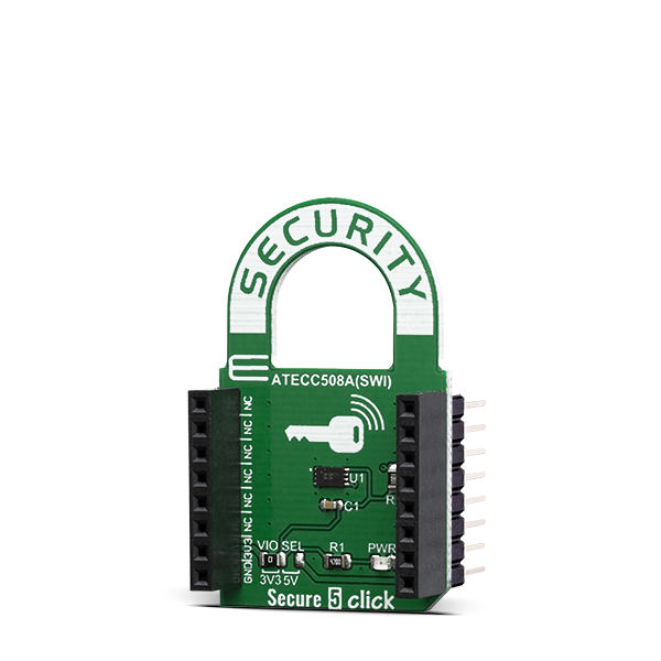
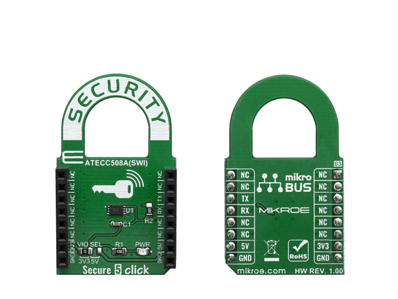
Secure 5 Click carries the ATECC508A cryptographic coprocessor with secure hardware-based key storage, from Microchip. The ATECC508A includes an EEPROM array which can be used for storage of up to 16 keys, certificates, miscellaneous read/write, read-only or secret data, consumption logging, and security configurations.

No Abuse Reported

Do you want to subscribe in order to receive notifications regarding "Secure 5 click" changes.

Do you want to unsubscribe in order to stop receiving notifications regarding "Secure 5 click" changes.

Do you want to report abuse regarding "Secure 5 click".

  • Information
  • Comments (0)
DOWNLOAD LINK RELATED COMPILER CONTAINS
  • lib
  • src
  • exa
  • hlp
  • hex
  • sch
  • pcb
  • doc

mikroSDK Library Blog

Secure 5 click

Secure 5 click

Native view of the Secure 5 click board.

View full image
Secure 5 click

Secure 5 click

Front and back view of the Secure 5 click board.

View full image

Library Description

The library demonstrates the operation of the software single wire interface implementation.

Key functions:

  • int8_t secureswi_init(T_SECURESWI_DIRSET inSet, T_SECURESWI_DIRSET outSet) - Initialize the SWI interface and pass the pin direction setting functions.
  • void secureswi_sendBytes(uint8_t len,uint8_t *stBuf) - Encode data buffer and send the data to the SWI bus.
  • void secureswi_receiveBytes(uint8_t len,uint8_t *stBuf) - Receive and decode data from the SWI bus.

Examples description

The application is composed of three sections :

  • System Initialization - Initialize the GPIO sturcture and configure the serial port for logging data.
  • Application Initialization - Initialize the driver and configure swi for communication.
  • Application Task - Data is read from the secure chip. If the readout is successful the data is then printed on the serial port in the hex format.
void applicationTask()
{
     uint8_t bufferOut[128];

     cfg_atsha204a_swi_default.iface_type  = ATCA_SWI_IFACE;
     cfg_atsha204a_swi_default.devtype     = ATSHA204A;
     cfg_atsha204a_swi_default.atcaswi.bus = 1;
     cfg_atsha204a_swi_default.wake_delay  = 2560;
     cfg_atsha204a_swi_default.rx_retries  = 10;

     atcab_init(&cfg_atsha204a_swi_default);

     mikrobus_logWrite("Starting test",_LOG_LINE);

     memset(bufferOut,0,127);

     if (atcab_read_serial_number(bufferOut) == ATCA_SUCCESS)
     {
         mikrobus_logWrite("rn Serial number: ",_LOG_LINE);
         secureswi_printHex(bufferOut,9);
     }
     else
     {
         mikrobus_logWrite("rn Reading serial number failed...",_LOG_LINE);
         secureswi_printHex(bufferOut,sizeof(bufferOut));
     }

     Delay_ms (1500);
     memset (bufferOut, 0x00, 128);
     if (atcab_read_config_zone(bufferOut) == ATCA_SUCCESS)
     {
        mikrobus_logWrite("rnrn First 32 bytes of device configuration: ",_LOG_LINE);
        secureswi_printHex(bufferOut,32);
     }
     else
     {
        mikrobus_logWrite("rnrn Reading config zone failed...",_LOG_LINE);
        secureswi_printHex(bufferOut,sizeof(bufferOut));
     }

     while(1)
     {

     }
}

Other mikroE Libraries used in the example:

  • Conversions
  • C_String
  • UART

Additional notes and informations

Depending on the development board you are using, you may need USB UART clickUSB UART 2 click or RS232 click to connect to your PC, for development systems with no UART to USB interface available on the board. The terminal available in all MikroElektronika compilers, or any other terminal application of your choice, can be used to read the message.

ALSO FROM THIS AUTHOR

PROXIMITY 7 Click

0

Proximity 7 Click is an advanced proximity and ambient light sensing Click board™. It features the ADPS9930, a digital sensor IC equipped with two photodiodes (PD) and an IR LED, driven by a proprietary LED driver circuit. It allows an accurate proximity detection for a maximum distance of 100mm.

[Learn More]

Hall Current 8 120A Click

0

Hall Current 8 Click is a compact add-on board that contains a precise solution for AC/DC current sensing. This board features the TLI4971-A120T5, a high-precision coreless current sensor for industrial/consumer applications from Infineon Technologies. The TLI4971-A120T5 has an analog interface and two fast overcurrent detection outputs, which support the protection of the power circuitry. Galvanic isolation is also provided according to the magnetic sensing principle. Infineon's monolithic Hall technology enables accurate and highly linear measurement of currents with a full scale up to 120A. This Click board™ is suitable for AC/DC current measurement applications: electrical drives, general-purpose inverters, chargers, current monitoring, overload, over-current detection, and many more.

[Learn More]

IR Sense 5 Click

0

IR Sense 5 Click is a compact add-on board designed for accurate, non-contact surface temperature measurement. This board features the ZTP-148SRC1, a thermopile IR sensor from Amphenol, with a measurement range from -20 to +100°C, an active area of 0.7x0.7mm², and a typical field of view of 85 degrees. The board also integrates an OPA2365AIDR OpAmp for signal amplification and an MCP3221 analog-to-digital converter for digitizing the output. Additional features include output offset selection and test points for signal monitoring.

[Learn More]