TOP Contributors

  1. MIKROE (2784 codes)
  2. Alcides Ramos (405 codes)
  3. Shawon Shahryiar (307 codes)
  4. jm_palomino (133 codes)
  5. Bugz Bensce (97 codes)
  6. S P (73 codes)
  7. dany (71 codes)
  8. MikroBUS.NET Team (35 codes)
  9. NART SCHINACKOW (34 codes)
  10. Armstrong Subero (27 codes)

Most Downloaded

  1. Timer Calculator (141699 times)
  2. FAT32 Library (74777 times)
  3. Network Ethernet Library (59219 times)
  4. USB Device Library (49226 times)
  5. Network WiFi Library (44999 times)
  6. FT800 Library (44536 times)
  7. GSM click (31200 times)
  8. mikroSDK (30103 times)
  9. microSD click (27586 times)
  10. PID Library (27543 times)
Libstock prefers package manager

Package Manager

We strongly encourage users to use Package manager for sharing their code on Libstock website, because it boosts your efficiency and leaves the end user with no room for error. [more info]

< Back
mikroSDK Library

6DOF IMU 7 Click

Rating:

5

Author: MIKROE

Last Updated: 2019-10-16

Package Version: 1.0.0.0

mikroSDK Library: 1.0.0.0

Category: Motion

Downloaded: 4204 times

Not followed.

License: MIT license  

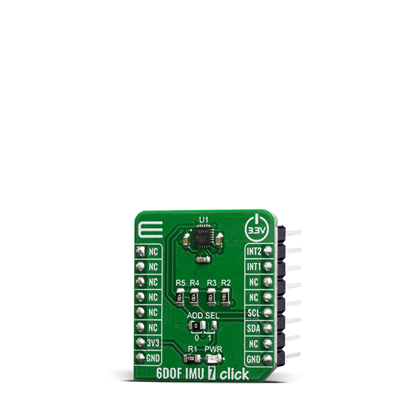
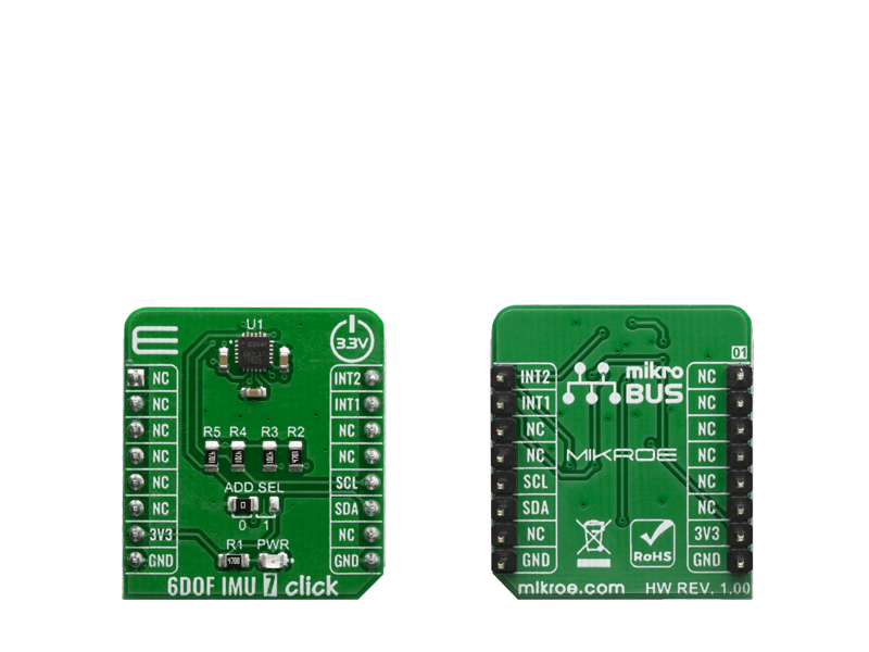
6DOF IMU 7 Click is an advanced 6-axis motion tracking Click board, which utilizes the ICM-20649, a high-performance integrated motion sensor, equipped with a 3-axis gyroscope, and a 3-axis accelerometer.

No Abuse Reported

Do you want to subscribe in order to receive notifications regarding "6DOF IMU 7 Click" changes.

Do you want to unsubscribe in order to stop receiving notifications regarding "6DOF IMU 7 Click" changes.

Do you want to report abuse regarding "6DOF IMU 7 Click".

  • mikroSDK Library 2.0.0.0
  • Comments (0)
DOWNLOAD LINK RELATED COMPILER CONTAINS
mikroBasic PRO for ARM
  • lib
  • src
  • exa
  • hlp
  • hex
  • sch
  • pcb
  • doc
mikroBasic PRO for AVR
  • lib
  • src
  • exa
  • hlp
  • hex
  • sch
  • pcb
  • doc
mikroBasic PRO for dsPIC30/33 & PIC24
  • lib
  • src
  • exa
  • hlp
  • hex
  • sch
  • pcb
  • doc
mikroBasic PRO for FT90x
  • lib
  • src
  • exa
  • hlp
  • hex
  • sch
  • pcb
  • doc
mikroBasic PRO for PIC
  • lib
  • src
  • exa
  • hlp
  • hex
  • sch
  • pcb
  • doc
mikroBasic PRO for PIC32
  • lib
  • src
  • exa
  • hlp
  • hex
  • sch
  • pcb
  • doc
mikroC PRO for ARM
  • lib
  • src
  • exa
  • hlp
  • hex
  • sch
  • pcb
  • doc
mikroC PRO for AVR
  • lib
  • src
  • exa
  • hlp
  • hex
  • sch
  • pcb
  • doc
mikroC PRO for dsPIC30/33 & PIC24
  • lib
  • src
  • exa
  • hlp
  • hex
  • sch
  • pcb
  • doc
mikroC PRO for FT90x
  • lib
  • src
  • exa
  • hlp
  • hex
  • sch
  • pcb
  • doc
mikroC PRO for PIC
  • lib
  • src
  • exa
  • hlp
  • hex
  • sch
  • pcb
  • doc
mikroC PRO for PIC32
  • lib
  • src
  • exa
  • hlp
  • hex
  • sch
  • pcb
  • doc
mikroPascal PRO for ARM
  • lib
  • src
  • exa
  • hlp
  • hex
  • sch
  • pcb
  • doc
mikroPascal PRO for AVR
  • lib
  • src
  • exa
  • hlp
  • hex
  • sch
  • pcb
  • doc
mikroPascal PRO for dsPIC30/33 & PIC24
  • lib
  • src
  • exa
  • hlp
  • hex
  • sch
  • pcb
  • doc
mikroPascal PRO for FT90x
  • lib
  • src
  • exa
  • hlp
  • hex
  • sch
  • pcb
  • doc
mikroPascal PRO for PIC
  • lib
  • src
  • exa
  • hlp
  • hex
  • sch
  • pcb
  • doc
mikroPascal PRO for PIC32
  • lib
  • src
  • exa
  • hlp
  • hex
  • sch
  • pcb
  • doc

mikroSDK Library Blog

6DOF IMU 7 click

6DOF IMU 7 click

Native view of the 6DOF IMU 7 click board.

View full image
6DOF IMU 7 click

6DOF IMU 7 click

Front and back view of the 6DOF IMU 7 click board.

View full image

Library Description

The library covers all the necessary functions that enables the usage of the 6DOF IMU 7 Click board. It initializes and defines the I2C bus driver and drivers that offer a plethora of settings. The library also offers functions that allow reading of accelerometer,gyroscope and dye temperature, as well as generic read and write function that offer reading( and writing) of different lenghts of data(byte, word or user defined number of bytes).

Key functions:

  • void c6dofimu7_Gyroscope( float *xGyro, float *yGyro, float *zGyro, float gyroSens ) - Function is used to get angular momentum.
  • void c6dofimu7_Accelerometer( float *xAccel, float *yAccel, float *zAccel, float accelSens ) - Function is used to get acceleration measurement.
  • float c6dofimu7_getTemperatureC( float tempSens, float tempOffset ) - Function is used to get temperature in degree.

Examples description

The application is composed of three sections :

  • System Initialization - Initializes I2C module, LOG and GPIO structures, sets INT and PWM pins as input.
  • Application Initialization - Initalizes I2C driver, applies default setup and writes an initial log.
  • Application Task - (code snippet)This example demonstrates the use of 6DOF IMU 7 Click board. It calculates angular momentum, acceleration measurement and temperature in degree Centigrade. Results are displayed on USART terminal.
void applicationTask()
{
    c6dofimu7_Gyroscope( &xGyro, &yGyro, &zGyro, gyroSens );
    
    FloatToStr( xGyro, logTxt );
    mikrobus_logWrite( "X angular rate: ", _LOG_LINE );
    Ltrim( logTxt );
    mikrobus_logWrite( logTxt, _LOG_LINE );
    
    FloatToStr( yGyro, logTxt );
    mikrobus_logWrite( "Y angular rate: ", _LOG_LINE );
    Ltrim( logTxt );
    mikrobus_logWrite( logTxt, _LOG_LINE );
    
    FloatToStr( zGyro, logTxt );
    mikrobus_logWrite( "Z angular rate: ", _LOG_LINE );
    Ltrim( logTxt );
    mikrobus_logWrite( logTxt, _LOG_LINE );
    mikrobus_logWrite( "---------------------", _LOG_LINE );
    
    c6dofimu7_Accelerometer( &xAccel, &yAccel, &zAccel, accelSens );

    FloatToStr( xAccel, logTxt );
    mikrobus_logWrite( "X acceleration rate: ", _LOG_LINE );
    Ltrim( logTxt );
    mikrobus_logWrite( logTxt, _LOG_LINE );

    FloatToStr( yAccel, logTxt );
    mikrobus_logWrite( "Y acceleration rate: ", _LOG_LINE );
    Ltrim( logTxt );
    mikrobus_logWrite( logTxt, _LOG_LINE );

    mikrobus_logWrite( "Z acceleration rate: ", _LOG_LINE );
    Ltrim( logTxt );
    FloatToStr( zAccel, logTxt );
    mikrobus_logWrite( logTxt, _LOG_LINE );
    mikrobus_logWrite( "---------------------", _LOG_LINE );
    
    temperature = c6dofimu7_getTemperatureC( tempSens, tempOffset );

    mikrobus_logWrite( "Temperature: ", _LOG_LINE );
    Ltrim( logTxt );
    FloatToStr( temperature, logTxt );
    mikrobus_logWrite( logTxt, _LOG_TEXT );
    mikrobus_logWrite( degCel, _LOG_LINE );
    mikrobus_logWrite( "---------------------", _LOG_LINE );
    
    Delay_ms( 1000 );
}

Other mikroE Libraries used in the example:

  • I2C
  • UART
  • Conversions

Additional notes and informations

Depending on the development board you are using, you may need USB UART clickUSB UART 2 click or RS232 click to connect to your PC, for development systems with no UART to USB interface available on the board. The terminal available in all MikroElektronika compilers, or any other terminal application of your choice, can be used to read the message.

ALSO FROM THIS AUTHOR

Brushless 4 click

5

Brushless 4 click is a 3 phase sensorless BLDC motor driver, which features a 180° sinusoidal drive, providing high efficiency and low acoustic noise. This type of drivers inherently provides higher torque in general, compared to classical 120° BLDC motor drivers.

[Learn More]

GNSS MAX Click

0

GNSS MAX Click is a compact add-on board that provides fast positioning capability. This board features the MAX-M10S, an ultra-low-power GNSS receiver for high-performance asset-tracking from u-blox. The MAX-M10S supports the concurrent reception of four GNSS (GPS, GLONASS, Galileo, and BeiDou), which maximizes the position availability, particularly under challenging conditions such as in deep urban canyons. It is built on the u-blox M10 GNSS platform, which provides exceptional sensitivity and acquisition times for all L1 GNSS systems. It also comes with a configurable host interface, and advanced jamming and spoofing detection.

[Learn More]

STSPIN820 Click

0

STSPIN820 Click is a stepper motor driver with the PWM current control, selectable microstepping up to 256 microsteps, and a wide voltage range. It is based on the STSPIN820, a stepper motor driver from STSPIN8 series. Designed to be a bullet-proof solution for the new wave of demanding industrial applications, it integrates two full-bridges with low ON resistance, the control logic, and a full set of protection features, in a small 4x4mm QFN package. Its output stage implements the PWM current control with the fixed OFF time. The device can be used with the step motor voltage ranging from 7V up to 45V, and current up to 1.5A per bridge.

[Learn More]