TOP Contributors

  1. MIKROE (2784 codes)
  2. Alcides Ramos (405 codes)
  3. Shawon Shahryiar (307 codes)
  4. jm_palomino (133 codes)
  5. Bugz Bensce (97 codes)
  6. S P (73 codes)
  7. dany (71 codes)
  8. MikroBUS.NET Team (35 codes)
  9. NART SCHINACKOW (34 codes)
  10. Armstrong Subero (27 codes)

Most Downloaded

  1. Timer Calculator (141629 times)
  2. FAT32 Library (74654 times)
  3. Network Ethernet Library (59128 times)
  4. USB Device Library (49167 times)
  5. Network WiFi Library (44926 times)
  6. FT800 Library (44459 times)
  7. GSM click (31122 times)
  8. mikroSDK (30037 times)
  9. microSD click (27531 times)
  10. PID Library (27512 times)
Libstock prefers package manager

Package Manager

We strongly encourage users to use Package manager for sharing their code on Libstock website, because it boosts your efficiency and leaves the end user with no room for error. [more info]

< Back
mikroSDK Library

DC MOTOR 10

Rating:

5

Author: MIKROE

Last Updated: 2019-12-09

Package Version: 1.0.0.0

mikroSDK Library: 1.0.0.0

Category: Brushed

Downloaded: 3874 times

Not followed.

License: MIT license  

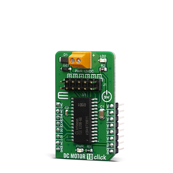
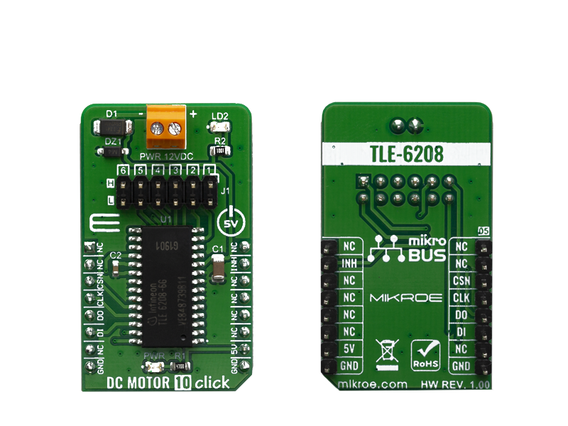
DC Motor 10 Click is a brushed DC motor driver with the current limiting and current sensing. It is based on the TLE 6208-6 G, an Hex-Half-Bridge / Double Six-Driver IC, optimized for motor driving applications.

No Abuse Reported

Do you want to subscribe in order to receive notifications regarding "DC MOTOR 10" changes.

Do you want to unsubscribe in order to stop receiving notifications regarding "DC MOTOR 10" changes.

Do you want to report abuse regarding "DC MOTOR 10".

  • mikroSDK Library 2.0.0.0
  • Comments (0)
DOWNLOAD LINK RELATED COMPILER CONTAINS
mikroBasic PRO for ARM
  • lib
  • src
  • exa
  • hlp
  • hex
  • sch
  • pcb
  • doc
mikroBasic PRO for AVR
  • lib
  • src
  • exa
  • hlp
  • hex
  • sch
  • pcb
  • doc
mikroBasic PRO for dsPIC30/33 & PIC24
  • lib
  • src
  • exa
  • hlp
  • hex
  • sch
  • pcb
  • doc
mikroBasic PRO for FT90x
  • lib
  • src
  • exa
  • hlp
  • hex
  • sch
  • pcb
  • doc
mikroBasic PRO for PIC
  • lib
  • src
  • exa
  • hlp
  • hex
  • sch
  • pcb
  • doc
mikroBasic PRO for PIC32
  • lib
  • src
  • exa
  • hlp
  • hex
  • sch
  • pcb
  • doc
mikroC PRO for ARM
  • lib
  • src
  • exa
  • hlp
  • hex
  • sch
  • pcb
  • doc
mikroC PRO for AVR
  • lib
  • src
  • exa
  • hlp
  • hex
  • sch
  • pcb
  • doc
mikroC PRO for dsPIC30/33 & PIC24
  • lib
  • src
  • exa
  • hlp
  • hex
  • sch
  • pcb
  • doc
mikroC PRO for FT90x
  • lib
  • src
  • exa
  • hlp
  • hex
  • sch
  • pcb
  • doc
mikroC PRO for PIC
  • lib
  • src
  • exa
  • hlp
  • hex
  • sch
  • pcb
  • doc
mikroC PRO for PIC32
  • lib
  • src
  • exa
  • hlp
  • hex
  • sch
  • pcb
  • doc
mikroPascal PRO for ARM
  • lib
  • src
  • exa
  • hlp
  • hex
  • sch
  • pcb
  • doc
mikroPascal PRO for AVR
  • lib
  • src
  • exa
  • hlp
  • hex
  • sch
  • pcb
  • doc
mikroPascal PRO for dsPIC30/33 & PIC24
  • lib
  • src
  • exa
  • hlp
  • hex
  • sch
  • pcb
  • doc
mikroPascal PRO for FT90x
  • lib
  • src
  • exa
  • hlp
  • hex
  • sch
  • pcb
  • doc
mikroPascal PRO for PIC
  • lib
  • src
  • exa
  • hlp
  • hex
  • sch
  • pcb
  • doc
mikroPascal PRO for PIC32
  • lib
  • src
  • exa
  • hlp
  • hex
  • sch
  • pcb
  • doc

mikroSDK Library Blog

DC MOTOR 10 click

DC MOTOR 10 click

Native view of the DC MOTOR 10 click board.

View full image
DC MOTOR 10 click

DC MOTOR 10 click

Front and back view of the DC MOTOR 10 click board.

View full image

Library Description

The library covers all the necessary functions that enables the usage of the DC Motor 10 Click board. It initializes and defines the SPI bus driver and drivers that allow full control of the device to the user. It is possible to enable up to 6 dc motors in hlaf bridge, or 5 with full bridge.

Key functions:

  • void dcmotor10_resetStatusReg(); - Function is used to reset status register.
  • void dcmotor10_enableChann1(); - Function is used to enable channel 1.
  • void dcmotor10_sendCommand( uint16_t wrData ); - Function is used to send command.

Examples description

The application is composed of three sections :

  • System Initialization - Initializes SPI module, LOG and GPIO structures, sets INT and CS pins as output.
  • Application Initialization - Initalizes SPI driver and uninhibits the device.
  • Application Task - (code snippet) This example demonstrates the use of DC MOTOR 10 click by running dc motors on channels 1 through 3, first all 3 together and then separately.
void applicationTask()
{
    dcmotor10_sendCommand(  _DCMOTOR10_ENABLE_1 | _DCMOTOR10_ENABLE_2 
                                                | _DCMOTOR10_ENABLE_3 );
    Delay_ms( 5000 );
    dcmotor10_enableChann1();
    Delay_ms( 5000 );
    dcmotor10_enableChann2();
    Delay_ms( 5000 );
    dcmotor10_enableChann3();
    Delay_ms( 5000 );
    dcmotor10_resetStatusReg();
    Delay_ms( 1000 );
}

Other mikroE Libraries used in the example:

  • SPI
  • UART
  • Conversions

Additional notes and informations

Depending on the development board you are using, you may need USB UART clickUSB UART 2 click or RS232 click to connect to your PC, for development systems with no UART to USB interface available on the board. The terminal available in all MikroElektronika compilers, or any other terminal application of your choice, can be used to read the message.

ALSO FROM THIS AUTHOR

mikromedia for PIC18FJ - Examples

5

Set of examples for mikromedia for PIC18FJ. Provided examples demonstrate working with mikromedia's various features and modules:
- Accelerometer
- MMC SD card
- MP3
- Serial Flash
- TFT
- Touch Panel
- USB

[Learn More]

Tamper 2 click

5

Tamper 2 click contains a levered D2HW-A221Dswitch by Omron, which outputs signal in both positions - pressed and released. The most common use of the Tamper 2 click is door opening or closing detection, detecting the end of travel of a linear actuator, a Morse code input device, etc.

[Learn More]

Comparator click

5

Comparator click can be used with a single or dual power supply. If a single power supply is used, the offset voltage can be as low as 2.0 mV, with a range from 2.0 VDC to 36 VDC. For dual supplies, the range is from ±1.0 VDC to ±18 VDC. The resulting output is compatible with TTL, DTL, ECL, MOS and CMOS logic systems.

[Learn More]