TOP Contributors

  1. MIKROE (2784 codes)
  2. Alcides Ramos (405 codes)
  3. Shawon Shahryiar (307 codes)
  4. jm_palomino (133 codes)
  5. Bugz Bensce (97 codes)
  6. S P (73 codes)
  7. dany (71 codes)
  8. MikroBUS.NET Team (35 codes)
  9. NART SCHINACKOW (34 codes)
  10. Armstrong Subero (27 codes)

Most Downloaded

  1. Timer Calculator (141914 times)
  2. FAT32 Library (75065 times)
  3. Network Ethernet Library (59358 times)
  4. USB Device Library (49356 times)
  5. Network WiFi Library (45169 times)
  6. FT800 Library (44737 times)
  7. GSM click (31307 times)
  8. mikroSDK (30272 times)
  9. microSD click (27690 times)
  10. PID Library (27577 times)
Libstock prefers package manager

Package Manager

We strongly encourage users to use Package manager for sharing their code on Libstock website, because it boosts your efficiency and leaves the end user with no room for error. [more info]

< Back
mikroSDK Library

RTC 10 click

Rating:

5

Author: MIKROE

Last Updated: 2019-10-11

Package Version: 1.0.0.0

mikroSDK Library: 1.0.0.0

Category: RTC

Downloaded: 4194 times

Not followed.

License: MIT license  

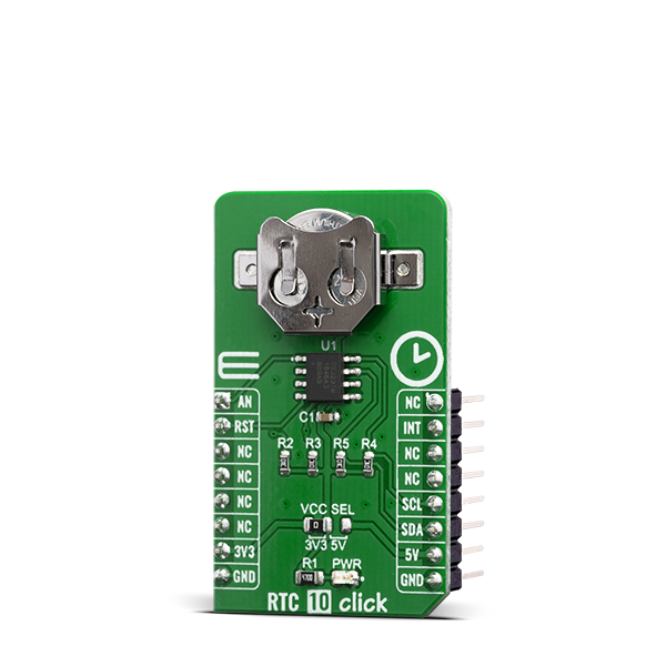
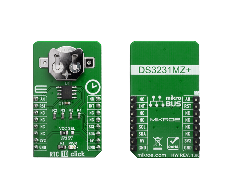
RTC 10 Click is a real time clock module which has an extremely low power consumption, allowing it to be used with a single button cell battery, for an extended period of time. It features the DS3231M, a low-cost, extremely accurate, I2C realtime clock (RTC) from Maxim Integrated.

No Abuse Reported

Do you want to subscribe in order to receive notifications regarding "RTC 10 click" changes.

Do you want to unsubscribe in order to stop receiving notifications regarding "RTC 10 click" changes.

Do you want to report abuse regarding "RTC 10 click".

  • mikroSDK Library 2.0.0.0
  • Comments (0)
DOWNLOAD LINK RELATED COMPILER CONTAINS
mikroBasic PRO for ARM
  • lib
  • src
  • exa
  • hlp
  • hex
  • sch
  • pcb
  • doc
mikroBasic PRO for AVR
  • lib
  • src
  • exa
  • hlp
  • hex
  • sch
  • pcb
  • doc
mikroBasic PRO for dsPIC30/33 & PIC24
  • lib
  • src
  • exa
  • hlp
  • hex
  • sch
  • pcb
  • doc
mikroBasic PRO for FT90x
  • lib
  • src
  • exa
  • hlp
  • hex
  • sch
  • pcb
  • doc
mikroBasic PRO for PIC
  • lib
  • src
  • exa
  • hlp
  • hex
  • sch
  • pcb
  • doc
mikroBasic PRO for PIC32
  • lib
  • src
  • exa
  • hlp
  • hex
  • sch
  • pcb
  • doc
mikroC PRO for ARM
  • lib
  • src
  • exa
  • hlp
  • hex
  • sch
  • pcb
  • doc
mikroC PRO for AVR
  • lib
  • src
  • exa
  • hlp
  • hex
  • sch
  • pcb
  • doc
mikroC PRO for dsPIC30/33 & PIC24
  • lib
  • src
  • exa
  • hlp
  • hex
  • sch
  • pcb
  • doc
mikroC PRO for FT90x
  • lib
  • src
  • exa
  • hlp
  • hex
  • sch
  • pcb
  • doc
mikroC PRO for PIC
  • lib
  • src
  • exa
  • hlp
  • hex
  • sch
  • pcb
  • doc
mikroC PRO for PIC32
  • lib
  • src
  • exa
  • hlp
  • hex
  • sch
  • pcb
  • doc
mikroPascal PRO for ARM
  • lib
  • src
  • exa
  • hlp
  • hex
  • sch
  • pcb
  • doc
mikroPascal PRO for AVR
  • lib
  • src
  • exa
  • hlp
  • hex
  • sch
  • pcb
  • doc
mikroPascal PRO for dsPIC30/33 & PIC24
  • lib
  • src
  • exa
  • hlp
  • hex
  • sch
  • pcb
  • doc
mikroPascal PRO for FT90x
  • lib
  • src
  • exa
  • hlp
  • hex
  • sch
  • pcb
  • doc
mikroPascal PRO for PIC
  • lib
  • src
  • exa
  • hlp
  • hex
  • sch
  • pcb
  • doc
mikroPascal PRO for PIC32
  • lib
  • src
  • exa
  • hlp
  • hex
  • sch
  • pcb
  • doc

mikroSDK Library Blog

RTC 10 click

RTC 10 click

Native view of the RTC 10 click board.

View full image
RTC 10 click

RTC 10 click

Front and back view of the RTC 10 click board.

View full image

Library Description

The library covers all the necessary functions to control RTC 10 click board. A library performs a standard I2C interface communication.

Key functions:

  • void rtc10_setTime( uint8_t timeHours, uint8_t timeMinutes, uint8_t timeSeconds ) - Set time hours, minutes and seconds function.
  • void rtc10_getTime( uint8_t *timeHours, uint8_t *timeMinutes, uint8_t *timeSeconds ) - Get time hours, minutes and seconds function.
  • void rtc10_setDate( uint8_t dayOfTheWeek, uint8_t dateDay, uint8_t dateMonth, uint16_t dateYear ) - Set date hours, minutes and seconds function.

Examples description

The application is composed of three sections :

  • System Initialization - Initializes GPIO, I2C and LOG structures, sets INT pin as input and RST pin as output and start to write log.
  • Application Initialization - Initialization driver enable's - I2C, hardware reset, set start time and date, enable counting also, write log.
  • Application Task - (code snippet) This is an example which demonstrates the use of RTC 10 Click board. RTC 10 Click communicates with register via I2C interface, set time and date, enable counting and display time and date values, also, display temperature value for every 1 sec. Results are being sent to the Usart Terminal where you can track their changes. All data logs write on Usart Terminal changes for every 1 sec.
void applicationTask()
{
    rtc10_getTime( &timeHours, &timeMinutes, &timeSeconds );
    Delay_10ms();

    rtc10_getDate( &dayOfTheWeek, &dateDay, &dateMonth, &dateYear );
    Delay_10ms();

    if ( secFlag !=  timeSeconds )
    {
        mikrobus_logWrite( " Time:  ", _LOG_TEXT );

        displayLogUart( timeHours );
        mikrobus_logWrite( ":", _LOG_TEXT );

        displayLogUart( timeMinutes );
        mikrobus_logWrite( ":", _LOG_TEXT );

        displayLogUart( timeSeconds );
        mikrobus_logWrite( "", _LOG_LINE );

        mikrobus_logWrite( " Date: ", _LOG_TEXT );

        displayLogUart( dateDay );
        mikrobus_logWrite( ".", _LOG_TEXT );

        displayLogUart( dateMonth );
        mikrobus_logWrite( ".", _LOG_TEXT );

        mikrobus_logWrite( "20", _LOG_TEXT );

        displayLogUart( dateYear );
        mikrobus_logWrite( ".", _LOG_LINE );
        
        displayDayOfTheWeek( dayOfTheWeek );
        
        if ( timeSeconds == 0 )
        {
            temperature = rtc10_getTemperature();

            mikrobus_logWrite( " Temp.: ", _LOG_TEXT );
            FloatToStr( temperature, logText );
            ltrim( logText );
            rtrim( logText );
            mikrobus_logWrite( logText, _LOG_TEXT );
            mikrobus_logWrite( degCel, _LOG_LINE );
        }

        mikrobus_logWrite( "-------------------", _LOG_LINE );

        secFlag =  timeSeconds;
    }
}


Additional Functions :

  • void displayLogDayOfTheWeek( uint8_t dayOfTheWeek ) - Write day of the week log on USART terminal.
  • void displayLogUart( uint8_t value ) - Write the value of time or date as a two-digit number.

Other mikroE Libraries used in the example:

  • I2C
  • UART
  • Conversions

Additional notes and informations

Depending on the development board you are using, you may need USB UART clickUSB UART 2 click or RS232 click to connect to your PC, for development systems with no UART to USB interface available on the board. The terminal available in all MikroElektronika compilers, or any other terminal application of your choice, can be used to read the message.

ALSO FROM THIS AUTHOR

DC Motor 14 Click

0

This IC includes one channel of motor output block, using a wide range of supply voltages, while delivering reasonably high current to the connected DC motors.

[Learn More]

MCP2518FD Click

0

MCP2518FD Click is a compact add-on board representing a complete CAN solution used as a control node in a CAN network. This board features the MCP2518FD, an external CAN FD controller with an SPI interface, and a high-speed CAN transceiver, the ATA6563, both from Microchip. The ATA6563, a low-level physical layer IC (PHY), provides a physical connection with the CAN bus itself, while the CAN controller MCP2518FD represents an interface between the MCU and the PHY. It features three operating modes with dedicated fail-safe features, remote wake-up via CAN, and ideally passive behavior when powered off on the CAN bus. This Click board™ is suitable for developing a wide range of automotive diagnostic applications, even on MCUs that do not natively support CAN interface.

[Learn More]

EEPROM 13 Click

0

EEPROM 13 Click is a compact add-on board that contains a highly reliable, nonvolatile memory solution. This board features the M24M01E, an electrically erasable programmable memory with enhanced hardware write protection for entire memory from STMicroelectronics. Its memory size of 1Mbit is organized as 128K words of 8bits each, with a page size of 256 bytes and an additional 256 bytes of identification page. The identification page can be used to store sensitive application parameters, which can be (later) permanently locked in read-only mode.

[Learn More]