TOP Contributors

  1. MIKROE (2784 codes)
  2. Alcides Ramos (405 codes)
  3. Shawon Shahryiar (307 codes)
  4. jm_palomino (133 codes)
  5. Bugz Bensce (97 codes)
  6. S P (73 codes)
  7. dany (71 codes)
  8. MikroBUS.NET Team (35 codes)
  9. NART SCHINACKOW (34 codes)
  10. Armstrong Subero (27 codes)

Most Downloaded

  1. Timer Calculator (141586 times)
  2. FAT32 Library (74538 times)
  3. Network Ethernet Library (59059 times)
  4. USB Device Library (49077 times)
  5. Network WiFi Library (44834 times)
  6. FT800 Library (44398 times)
  7. GSM click (31067 times)
  8. mikroSDK (29932 times)
  9. microSD click (27504 times)
  10. PID Library (27492 times)
Libstock prefers package manager

Package Manager

We strongly encourage users to use Package manager for sharing their code on Libstock website, because it boosts your efficiency and leaves the end user with no room for error. [more info]

< Back
mikroSDK Library

6DOF IMU 11 click

Rating:

5

Author: MIKROE

Last Updated: 2019-12-02

Package Version: 1.0.0.0

mikroSDK Library: 1.0.0.0

Category: Motion

Downloaded: 3712 times

Not followed.

License: MIT license  

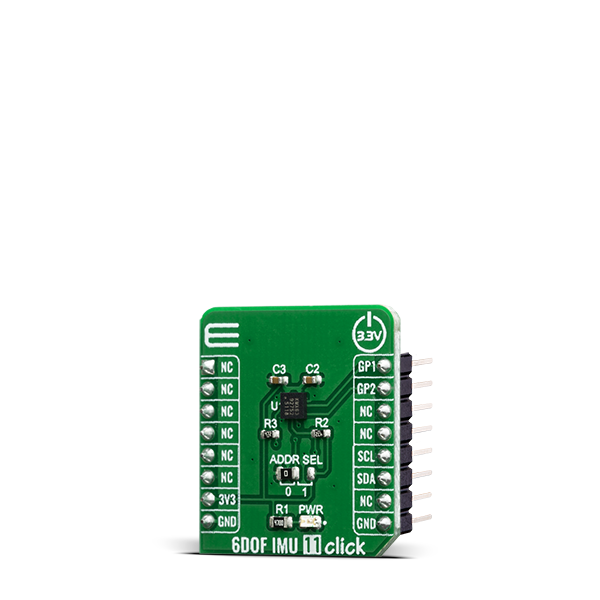
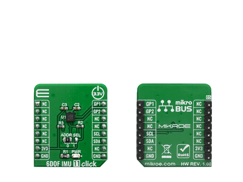
The 6DOF IMU 11 click is a Click board based on the KMX63, a 6 Degrees-of-Freedom inertial sensor system on a single, silicon chip, which is designed to strike a balance between current consumption and noise performance with excellent bias stability over temperature.

No Abuse Reported

Do you want to subscribe in order to receive notifications regarding "6DOF IMU 11 click" changes.

Do you want to unsubscribe in order to stop receiving notifications regarding "6DOF IMU 11 click" changes.

Do you want to report abuse regarding "6DOF IMU 11 click".

  • mikroSDK Library 2.0.0.0
  • Comments (0)
DOWNLOAD LINK RELATED COMPILER CONTAINS
mikroBasic PRO for ARM
  • lib
  • src
  • exa
  • hlp
  • hex
  • sch
  • pcb
  • doc
mikroBasic PRO for AVR
  • lib
  • src
  • exa
  • hlp
  • hex
  • sch
  • pcb
  • doc
mikroBasic PRO for dsPIC30/33 & PIC24
  • lib
  • src
  • exa
  • hlp
  • hex
  • sch
  • pcb
  • doc
mikroBasic PRO for FT90x
  • lib
  • src
  • exa
  • hlp
  • hex
  • sch
  • pcb
  • doc
mikroBasic PRO for PIC
  • lib
  • src
  • exa
  • hlp
  • hex
  • sch
  • pcb
  • doc
mikroBasic PRO for PIC32
  • lib
  • src
  • exa
  • hlp
  • hex
  • sch
  • pcb
  • doc
mikroC PRO for ARM
  • lib
  • src
  • exa
  • hlp
  • hex
  • sch
  • pcb
  • doc
mikroC PRO for AVR
  • lib
  • src
  • exa
  • hlp
  • hex
  • sch
  • pcb
  • doc
mikroC PRO for dsPIC30/33 & PIC24
  • lib
  • src
  • exa
  • hlp
  • hex
  • sch
  • pcb
  • doc
mikroC PRO for FT90x
  • lib
  • src
  • exa
  • hlp
  • hex
  • sch
  • pcb
  • doc
mikroC PRO for PIC
  • lib
  • src
  • exa
  • hlp
  • hex
  • sch
  • pcb
  • doc
mikroC PRO for PIC32
  • lib
  • src
  • exa
  • hlp
  • hex
  • sch
  • pcb
  • doc
mikroPascal PRO for ARM
  • lib
  • src
  • exa
  • hlp
  • hex
  • sch
  • pcb
  • doc
mikroPascal PRO for AVR
  • lib
  • src
  • exa
  • hlp
  • hex
  • sch
  • pcb
  • doc
mikroPascal PRO for dsPIC30/33 & PIC24
  • lib
  • src
  • exa
  • hlp
  • hex
  • sch
  • pcb
  • doc
mikroPascal PRO for FT90x
  • lib
  • src
  • exa
  • hlp
  • hex
  • sch
  • pcb
  • doc
mikroPascal PRO for PIC
  • lib
  • src
  • exa
  • hlp
  • hex
  • sch
  • pcb
  • doc
mikroPascal PRO for PIC32
  • lib
  • src
  • exa
  • hlp
  • hex
  • sch
  • pcb
  • doc

mikroSDK Library Blog

6DOF IMU 11 click

6DOF IMU 11 click

Native view of the 6DOF IMU 11 click board.

View full image
6DOF IMU 11 click

6DOF IMU 11 click

Front and back view of the 6DOF IMU 11 click board.

View full image

Library Description

The library covers all the necessary functions to control 6DOF IMU 11 click board. Library performs a standard I2C interface communication.

Key functions:

  • void c6dofimu11_set_default_sensor_config ( void ) - Set default sensor configuration function.
  • void c6dofimu11_read_accel ( c6dofimu11_accel_t *accel_data ) - Get Accel range X, Y and Z value function.
  • void c6dofimu11_read_mag ( c6dofimu11_mag_t *mag_data ) - Get Magnetometer magnetic field strength X, Y and Z value ( nT ) function.

Examples description

The application is composed of three sections :

  • System Initialization - Initializes I2C and start to write log.
  • Application Initialization - Initialization driver enables - I2C, check device ID, sets default configuration, also write log.
  • Application Task - (code snippet) This is an example which demonstrates the use of 6DOF IMU 11 Click board. Measured and display Accel and Magnetometer magnetic field strength values for X-axis, Y-axis and Z-axis. Results are being sent to the Usart Terminal where you can track their changes. All data logs write on USB uart changes for every 2 sec.
void application_task ( )
{
    c6dofimu11_read_accel ( &accel_data );
    Delay_ms( 10 );
    c6dofimu11_read_mag ( &mag_data );
    Delay_ms( 10 );

    mikrobus_logWrite( " Accel X : ", _LOG_TEXT );
    FloatToStr( accel_data.x, log_text );
    c6dofimu11_uart_sign_print( );
    mikrobus_logWrite( log_text, _LOG_TEXT );
    mikrobus_logWrite( " g", _LOG_LINE );

    mikrobus_logWrite( " Accel Y : ", _LOG_TEXT );
    FloatToStr( accel_data.y, log_text );
    c6dofimu11_uart_sign_print( );
    mikrobus_logWrite( log_text, _LOG_TEXT );
    mikrobus_logWrite( " g", _LOG_LINE );

    mikrobus_logWrite( " Accel Z : ", _LOG_TEXT );
    FloatToStr( accel_data.z, log_text );
    c6dofimu11_uart_sign_print( );
    mikrobus_logWrite( log_text, _LOG_TEXT );
    mikrobus_logWrite( " g", _LOG_LINE );
    mikrobus_logWrite( "- - - - - - - - - - - - - ", _LOG_LINE );

    mikrobus_logWrite( " Mag X   : ", _LOG_TEXT );
    FloatToStr( mag_data.x, log_text );
    c6dofimu11_uart_sign_print( );
    mikrobus_logWrite( log_text, _LOG_TEXT );
    mikrobus_logWrite( " uT", _LOG_LINE );

    mikrobus_logWrite( " Mag Y   : ", _LOG_TEXT );
    FloatToStr( mag_data.y, log_text );
    c6dofimu11_uart_sign_print( );
    mikrobus_logWrite( log_text, _LOG_TEXT );
    mikrobus_logWrite( " uT", _LOG_LINE );

    mikrobus_logWrite( " Mag Z   : ", _LOG_TEXT );
    FloatToStr( mag_data.z, log_text );
    c6dofimu11_uart_sign_print( );
    mikrobus_logWrite( log_text, _LOG_TEXT );
    mikrobus_logWrite( " uT", _LOG_LINE );
    mikrobus_logWrite( "--------------------------", _LOG_LINE );
    Delay_ms( 1000 );
}


Additional Functions :

  • void c6dofimu11_uart_sign_print ( ) - For beauty reasons in displaying the data log, this function inserts "+" sign when positive values have been read.

Other mikroE Libraries used in the example:

  • I2C
  • UART
  • Conversions

Additional notes and informations

Depending on the development board you are using, you may need USB UART clickUSB UART 2 click or RS232 click to connect to your PC, for development systems with no UART to USB interface available on the board. The terminal available in all MikroElektronika compilers, or any other terminal application of your choice, can be used to read the message.

ALSO FROM THIS AUTHOR

STSPIN220 Click

0

STSPIN220 Click is a stepper motor driver with the PWM current control and selectable microstepping up to 256 microsteps. It is based on the STSPIN220, a low voltage stepper motor driver from STSPIN2 series. It is optimized for battery-powered, low voltage motor driving applications, featuring the lowest standby current available on the market (max 80 nA). The STSPIN220 is a high-efficiency motor driver, featuring low ON resistance MOSFETs as the output stage, in a small 3x3mm QFN package. Its output stage implements the PWM current control with fixed OFF time, along with a full set of protection features. The device can be used with the step motor voltage ranging from 1.8V to 10V, and current up to 1.3A per bridge.

[Learn More]

Multi Stepper TB62261 Click

0

Multi Stepper Click is a compact add-on board that contains a bipolar stepper motor driver. This board features the TB62261FTG, a PHASE-in controlled bipolar stepping motor driver from Toshiba Semiconductor. It supports a PWM constant-current control drive and full-, half-, and quarter-step operation for less motor noise and smoother control. It has a wide operating voltage range of 10V to 38V with an output current capacity of 1.2A in addition to several built-in error detection circuits.

[Learn More]

GSM click

0

GSM click is the easiest way to add GSM/GPRS communication to your device. The click features Telit's GL865-QUAD. GSM click runs either on 3.3V or 5V power supply and communicates with the target microcontroller via UART interface.

[Learn More]